
Display system for suspending visuals for exhibit, training or advertising

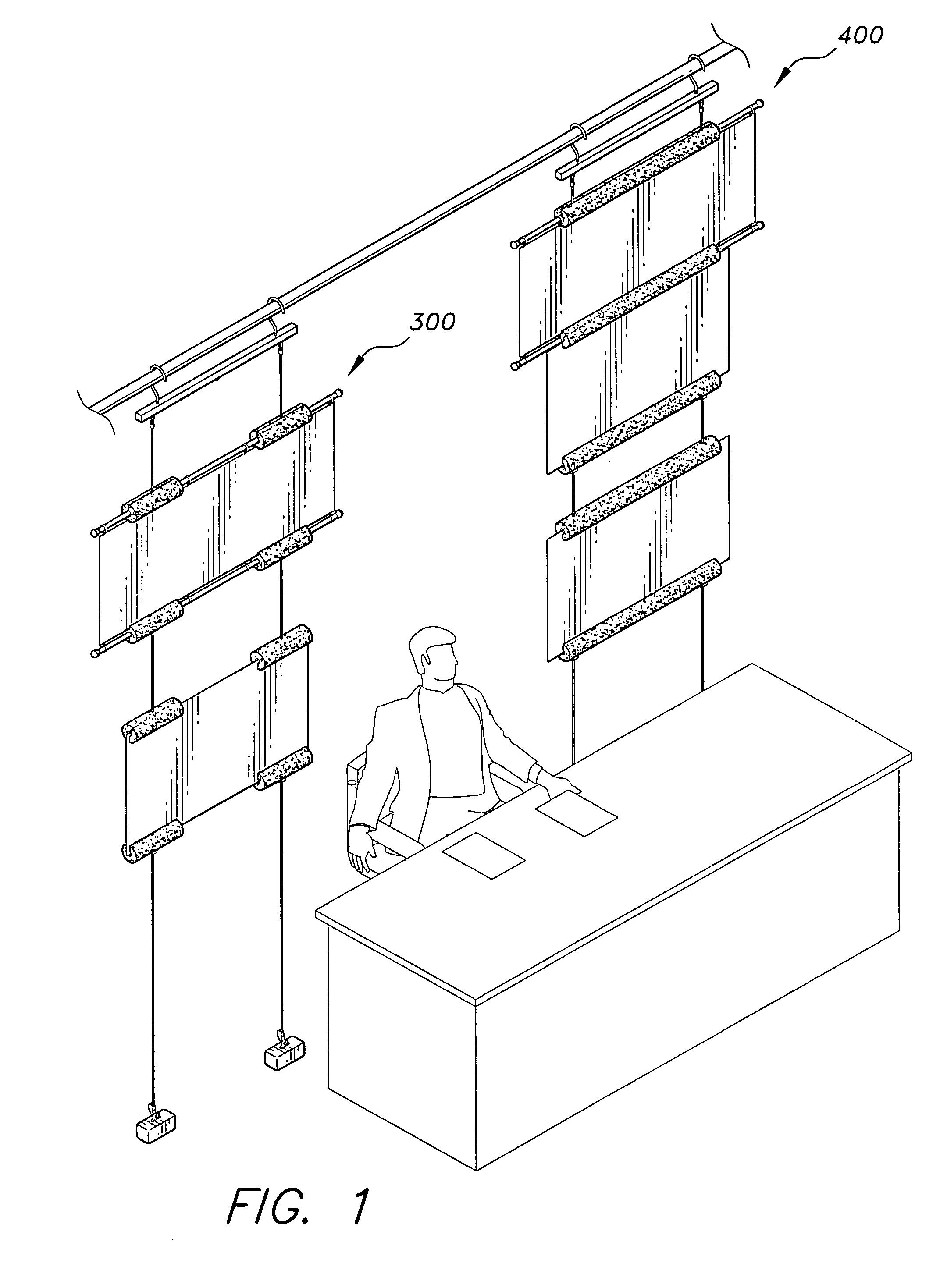
a technology for suspending visuals and displays, applied in the field of display systems for suspending visuals, can solve the problems of not being useful on the set of a local television station, inability to adjust the height or angle of the displayed article, and prior art devices for displaying signs and banners have several known drawbacks, so as to minimize the reflection of studio lighting into the camera, easy to store, and easy to install and remove.

Inactive Publication Date: 2006-08-08
VOLUCKAS STANLEY A
View PDF22 Cites 49 Cited by
  • Summary
  • Abstract
  • Description
  • Claims
  • Application Information

AI Technical Summary

Benefits of technology

"The invention is a display system for advertising, training, and exhibits that is portable, easy to install and remove, and can be adjusted to different heights and angles. It is made up of commercially available items that are assembled in a unique way to suspend signs and banners from a ceiling or lighting grid. The system is particularly useful for local television stations. The technical effects of the invention include its portability, adjustability, and ability to display both banners and signs on foam board. It is also affordable and easy to assemble."

Problems solved by technology

Prior art devices for displaying signs and banners have several known drawbacks and, in general, are not useful on the set of a local television station.
Known drawbacks of these devices include the inability to adjust the height or the angle of the displayed article, the complexity of installing and removing the display, lack of portability, and the likelihood of tipping over.
Most of these devices are limited to use with only one type of display article, i.e., a either a sign or a banner.

Method used


Image

  • Display system for suspending visuals for exhibit, training or advertising
  • Display system for suspending visuals for exhibit, training or advertising
  • Display system for suspending visuals for exhibit, training or advertising

Examples


embodiment 710

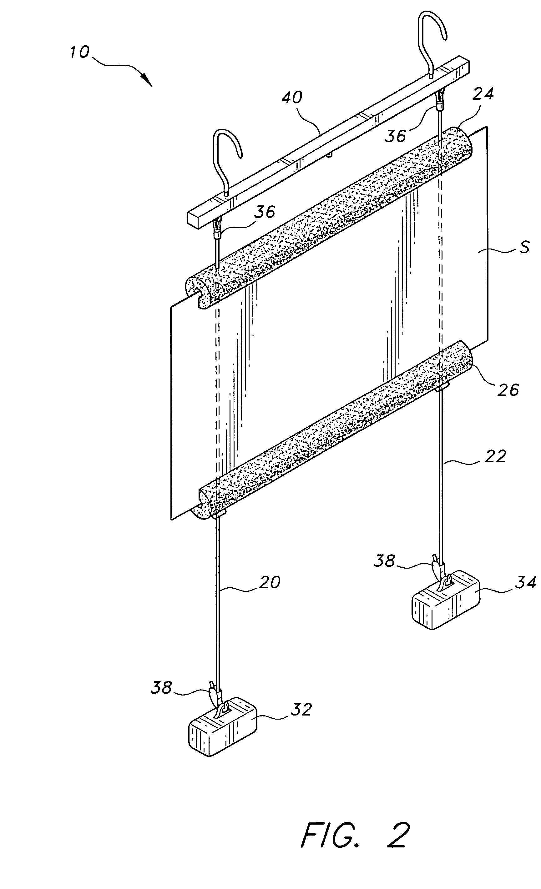
[0043]Each of the slotted tubular members 24 and 26, is a pool toy generically known as a pool noodle with a slot 56 and 58 and two holes 60 and 62 cut into each of the pool noodles. Such pool noodles are commercially available from pool equipment businesses. FIGS. 7, 8A and 8B illustrate an alternative embodiment of the slotted tubular members 710 and 712 that is constructed of a rectangular sheet of hard plastic 710 formed into a slotted tube by rolling two edges 702 and 703 of the sheet 710 inward toward one side of the sheet 710. The slot 701 is formed by a space left between the two edges 702 and 703. This alternative embodiment 710 is commercially available from a business entity doing business as Custom Plastics, Inc.

[0044]The two cord lock members 28 and 30, are constructed of hard plastic and are commercially available.

[0045]The two floor anchor members 32 and 34, are constructed of a molded metal. Other heavy objects or weights can also serve as floor anchor members.

[0046]...

embodiment 100

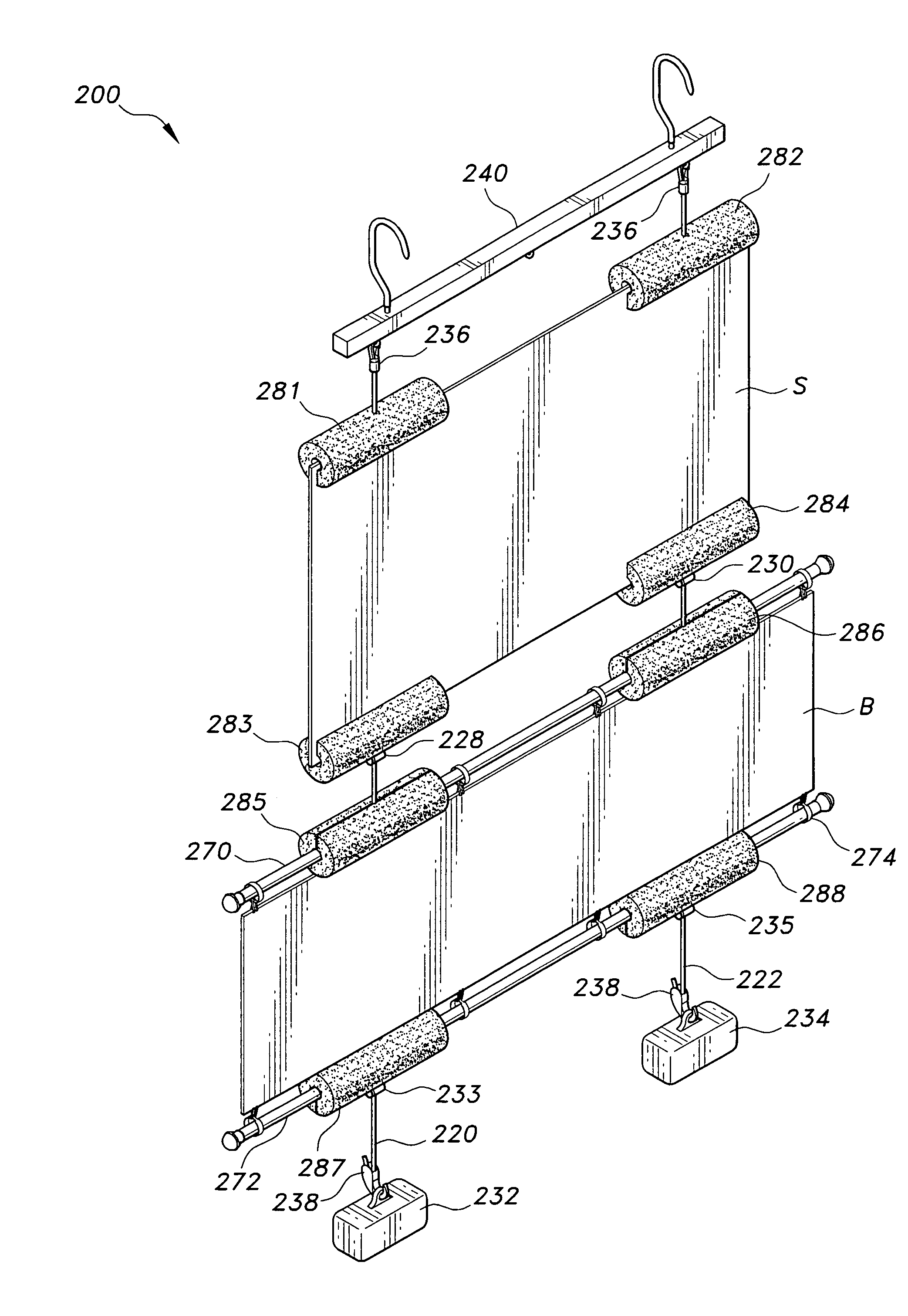
[0050]In this embodiment 100, the tubular members 124 and 126 are oriented differently in order to support the elongated rods 170 and 172. The upper tubular member 124 is oriented with its apertures below its slot 156, and rests on top of the cord lock members 128 and 130 thereby being held in position on the cords 120 and 122 by the cord lock members 128 and 130. The lower tubular member 126 is oriented with its apertures above its slot 158.

[0051]An elongated rod 170 and 172 passes through the cavity 150 and 152 in each of the tubular members 124 and 126. Each rod 170 and 172 is longer than its corresponding tubular member 124 and 126 and therefore portions of each rod 170 and 172 extend beyond each of the ends of each corresponding tubular member 124 and 126. Banner clips 174 hanging from the portions of the upper elongated rod 170 extending out of the upper tubular member 124 are clipped to the top edge of a banner B, thereby supporting the banner B. Banner clips 174 secured to t...


PUM


Abstract

A display system for suspending visuals for exhibit, training or advertising made up of an assembly of commercially available items, and used to display a banner or sign in a manner that is particularly useful on the set of a local television station. One embodiment has elastic cords, slotted tubular members, floor anchors, cord hooks, cord locks and a ceiling interface. When a rigid sign is situated with its bottom edge positioned in the lower tubular member slot and its top edge in the upper tubular member slot, the sign is suspended for viewing. In another embodiment, horizontal rods are supported by two tubular members with portions of the rods extended beyond the ends the tubular members. Several banner clips are used to clip a banner to the portions of the rods extending beyond the ends of the tubular members to suspend the banner for viewing. Other embodiments incorporate more than one set of either slotted tubular members or rod-supporting tubular members, or a combination of slotted tubular members and rod-supporting tubular members.

Description

BACKGROUND OF THE INVENTION[0001]1. Field of the Invention[0002]The present invention relates to the display of signs and banners, and more particularly, to a system for displaying signs and banners that uses a combination of commercially available items to quickly and easily suspend a sign or banner from a ceiling or lighting grid in such a manner that allows for easy adjustment of the height and angle of the displayed article. The invention is particularly useful on the sets of local television stations.[0003]2. Description of the Related Art[0004]Prior art devices for displaying signs and banners have several known drawbacks and, in general, are not useful on the set of a local television station. Known drawbacks of these devices include the inability to adjust the height or the angle of the displayed article, the complexity of installing and removing the display, lack of portability, and the likelihood of tipping over.[0005]To be useful on a television set, a display device must...

Claims


Application Information

Patent Timeline
Patent Type & Authority Patents(United States)
IPC IPC(8): G09F7/22G09F7/20G09F17/00
CPCG09F7/20G09F17/00G09F2017/0041G09F2007/186G09F7/205
Inventor VOLUCKAS, STANLEY A.
Owner VOLUCKAS STANLEY A
Learn More