
Method for debugging of analog and mixed-signal behavioral models during simulation

a behavioral model and simulation technology, applied in the field of simulation and testing technology, can solve problems such as complicated process, slow or expensive analog simulation, and complicating process

Inactive Publication Date: 2006-08-01
CADENCE DESIGN SYST INC
View PDF14 Cites 21 Cited by
  • Summary
  • Abstract
  • Description
  • Claims
  • Application Information

AI Technical Summary

Benefits of technology

[0041]The invention provides a capability of interactively debugging the behavioral code in analog or mixed-signal behavioral models, and a capability of debugging the interaction of such models in the design, by allowing circuit unknowns, such as node voltages, throughout the design to be interactively inspected as the simulation progresses. The method according to the invention has substantially modified the prior art solution by limiting the debugging interaction steps in a replay of the last iteration of the accepted timepoints. Using this method, the user only interacts with the simulation during the iteration replay, and only for the accepted solution points. If the user is single stepping through the simulation, the simulator enters interactive mode at each statement during the replay. Similarly, if not single stepping, but a breakpoint has been triggered, the simulator enters the interactive mode at the appropriate statement to honor the breakpoint only during the iteration replay. While the iteration replay is performed, the system of equations does not need to be solved again. Instead, the solution vector is reinstated from the known solution of the last iteration.

Problems solved by technology

The process is complicated by the fact that at a particular trial timepoint, the iterations may fail to converge, or may converge too slowly.
There may be also other reasons for rejecting a trial timepoint and choosing an earlier timepoint, which further complicate the process.
The repeated nature of building and solving such systems of equations for each iteration of each timepoint explains why analog simulation is considered slow or expensive compared to digital simulation, which operates at an entirely different level of abstraction and uses a completely different algorithm.
Analog simulation involves solving systems of equations, which translates into matrix inversion operations, and these are computationally expensive.
The disadvantages of the prior art solution are numerous.
The transient simulation algorithm described above is complicated by the fact that a trial timepoint solution may be rejected for various reasons.
Such reasons include synchronization with the digital engine in a mixed signal simulation, violation of the Local Truncation Error (LTE) requirements in the integration method used as part of the transient analysis to handle the differential part of the non-linear differential equations, and device limitation, etc.
Users such as circuit designer and modeling engineer are not generally familiar with the underlying intricacies of analog simulation and transient analysis algorithms.
They may consider time to be monotonically increasing.
If they observe the value of time moving forwards and backwards during debugging, they may feel confused.
Therefore, simply hiding the time from users is not a viable solution.
Since the solutions at these timesteps are then completely discarded by the simulator, the user may have wasted a substantial amount of time while single stepping through these solutions.
Again, it is confusing to the user in an iterative situation and time consuming and wasteful to stop before every evaluation of every statement.
This may further confuse the user and waste even more time as he single steps through each iteration and observes what appears to be radically different behavior from one iteration to the next.
A generic “watch” on all write attempts to a variable as would be implemented using standard sequential program debugging approaches would thus result in a lot of wasted stopping points.
Again, some of these may be on timepoints that are subsequently rejected, which is completely wasteful.
In addition, if non-monotonicity of time exists, a user who pays close attention to changes in a particular variable but not-very-close attention to the actual simulation time may observe what he considers to be very strange behavior.
However, because the timepoint sequence is not increasing monotonically, the variable cannot increase monotonically either.
This, again, leads to a potential source of user confusion and lack of confidence in the product.
Another drawback would be for the user who is watching value changes on a variable that is supposed to represent a voltage on some circuit node, or some function of the voltage.
However, due to the nature of Newton-Raphson iteration, a succession of guesses at a node voltage may oscillate quite a bit before finally converging on the actual solution.
While the actual solutions may be increasing monotonically, the individual solutions as part of the Newton-Raphson process are not likely to be, thus again confusing the user who is monitoring a variable that depends linearly on the node voltage.
By having the simulator check if it needs to present an interactive prompt before every single evaluation of every statement, for every iteration and for every trial timepoint (accepted or not), simulation time is wasted.
Hence this method is computationally inefficient and can degrade simulation performance by performing many possibly redundant checks.
Additionally, for object value change / access breakpoints, much time may be spent in checking every access of a particular variable, contributing to further inefficiency.
A drawback of exposing every single timepoint, whether accepted or not, is that the algorithm which decides when a particular timepoint is rejected is also exposed.

Method used


Image

  • Method for debugging of analog and mixed-signal behavioral models during simulation
  • Method for debugging of analog and mixed-signal behavioral models during simulation
  • Method for debugging of analog and mixed-signal behavioral models during simulation

Examples


Embodiment Construction

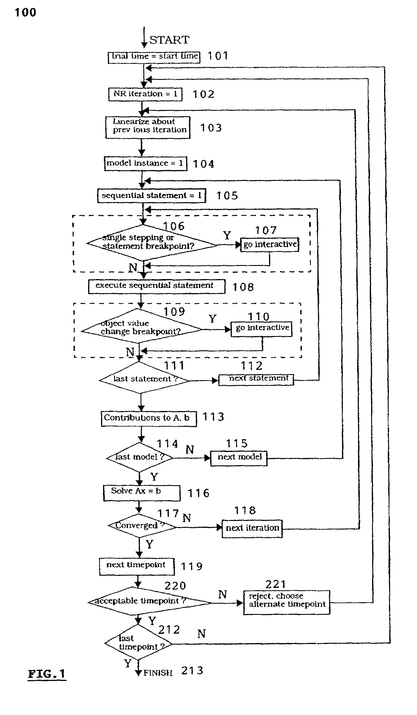
[0044]Referring to FIG. 1, which is a flowchart for a standard analog module debugging approach which represents the prior art solution, the dashed line boxes including the steps 106–107 and 109–110 indicate the areas to which this invention has made modifications.

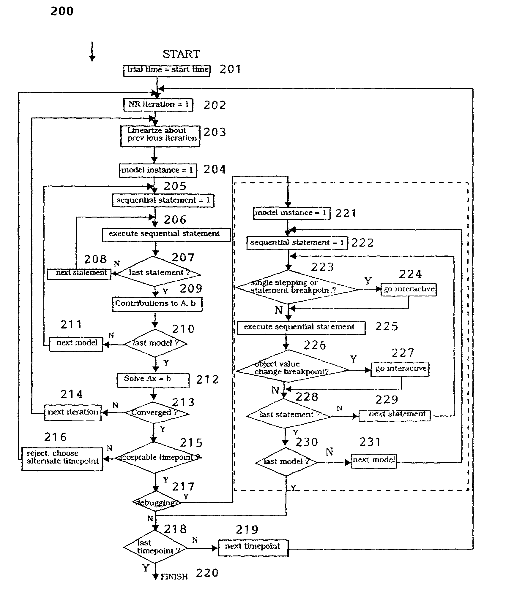
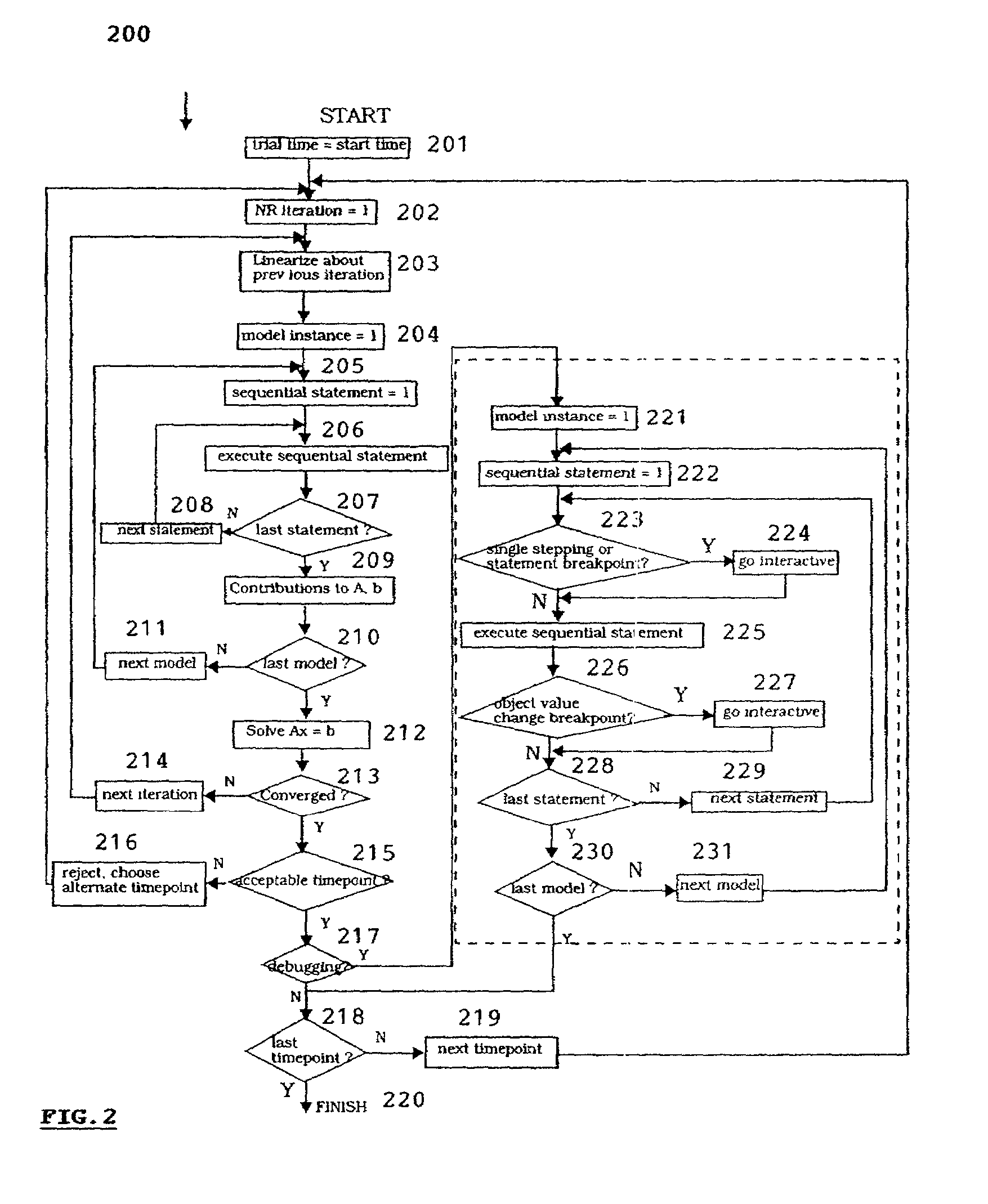
[0045]FIG. 2 is a flowchart illustrating the modifications to the transient analysis algorithm for enhanced debugging of analog behavioral code in analog and mixed-signal behavioral models according to the invention. The dashed box to the right of FIG. 2 including steps 221–231 replaces the two dashed boxes in FIG. 1. This replacement constitutes the enhancements to the standard transient analysis algorithm.

[0046]From Step 201 to Step 217, the standard transient analysis algorithm is followed regularly. The simulator sets a trial time 201; initializes Newton-Raphson iteration 202; linearizes about the previous iteration 203; and chooses model instance 204. Once the behavioral statements for each model have finished evaluat...


PUM


Abstract

An improved method for debugging of analog and mixed signal behavioral models during simulation using Newton-Raphson iteration replay. The method according to the invention has substantially modified the prior art solution by limiting the interactive debugging steps in a replay of the last iteration of the accepted timepoints. Using this method, the user only interacts with the simulation during the iteration replay, and only for the accepted solution points. If the user is single stepping through this simulation, the simulator enters interactive mode at each statement during the replay. Similarly, if not single stepping, but a breakpoint has been triggered, the simulator enters the interactive mode at the appropriate statement to honor the breakpoint. While the iteration replay is performed, the system of equations does not need to be solved again. Instead, the solution vector is reinstated from the known solution of the last iteration.

Description

FIELD OF THE INVENTION[0001]The invention relates generally to simulation and testing technology. More particularly, the invention relates to an improved method for debugging of analog and mixed signal behavioral models during simulation. We denote this method as Newton-Raphson iteration replay.BACKGROUND OF THE INVENTION[0002]Analog circuit simulations, whether purely analog or the analog content of a mixed-signal design, can be performed as part of a DC analysis in which a circuit operating point is determined. Simulations may also be performed as part of a transient analysis in which circuit behavior is determined as a function of time. The analog solution process formulates a system of non-linear differential equations representing the design at the DC operating point or at each timepoint during a transient analysis. It then solves the equations using some iterative technique. The solution to this system of equations gives the DC operating point of the circuit during the DC anal...

Claims


Application Information

Patent Timeline
Patent Type & Authority Patents(United States)
IPC IPC(8): G06F17/50
CPCG06F17/5036G06F30/367
Inventor O'RIORDAN, DONALD J.TRIHY, RICHARD
Owner CADENCE DESIGN SYST INC
Learn More