Eureka AIR delivers breakthrough ideas for toughest innovation challenges, trusted by R&D personnel around the world.

Disk drive including pivot-bearing cartridge tolerance ring having a damping layer for actuator resonance reduction

a technology of damping layer and actuator, which is applied in the direction of casing/cabinet/drawer details, instruments, casings/cabinets/drawers, etc., can solve the problems of actuator assembly exhibiting undesirable resonance, unwanted resonance, and affecting the operation of the driv

Inactive Publication Date: 2006-08-01
WESTERN DIGITAL TECH INC
View PDF11 Cites 84 Cited by
  • Summary
  • Abstract
  • Description
  • Claims
  • Application Information

AI Technical Summary

Problems solved by technology

As the actuator is controlled to move ever faster, unwanted resonances occur that are detrimental to the operation of the drive.
Although disk drive designers strive to render the actuator assembly as stiff as possible, it is still subject to bending when forces incident to the normal operation of the drive act upon it.
In particular, the actuator assembly may exhibit undesirable resonances, such as the so-called butterfly mode resonance (also called the main mechanical system mode or the first principal bending mode of actuator), in which the actuator elastically bends about the pivot-bearing cartridge.
However, even though the butterfly mode frequency increases, the amplitude of the corresponding resonance peak, as measured on a Bode plot, may still be unacceptably high.
However, it is believed that manufacturing such a dual metal laminate tolerance is difficult, impractical and expensive.
This, however, tends to delaminate the dual metal laminate structure of the tolerance ring.
If, however, the sheets are not pressed against the gears at the same time, the resulting indentations on both sheets likely will be offset relative to one another, further promoting delamination of the laminate structure or further difficulties in laminating the dual metal laminate tolerance ring in the first place.

Method used


Image

  • Disk drive including pivot-bearing cartridge tolerance ring having a damping layer for actuator resonance reduction
  • Disk drive including pivot-bearing cartridge tolerance ring having a damping layer for actuator resonance reduction
  • Disk drive including pivot-bearing cartridge tolerance ring having a damping layer for actuator resonance reduction

Examples


Embodiment Construction

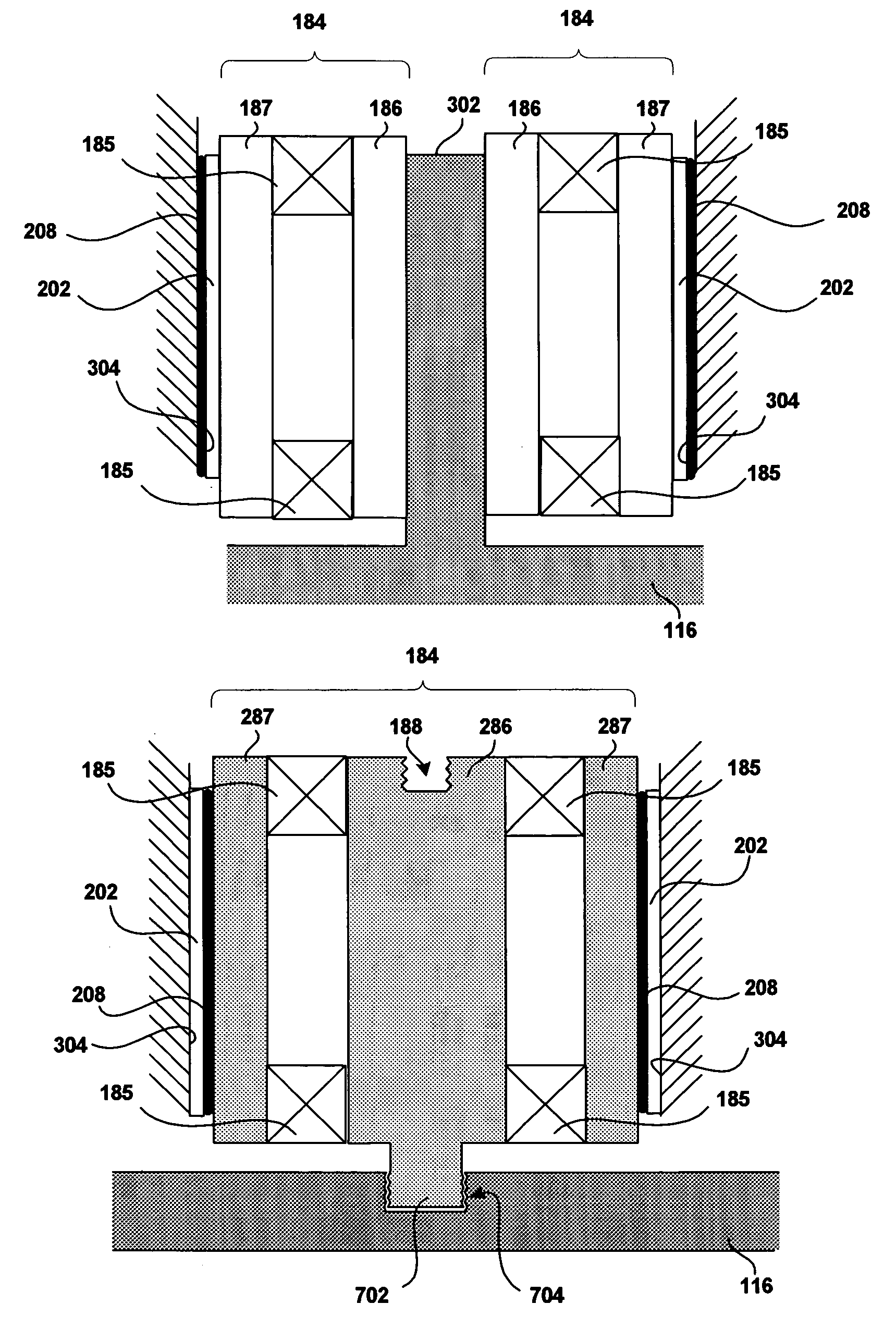
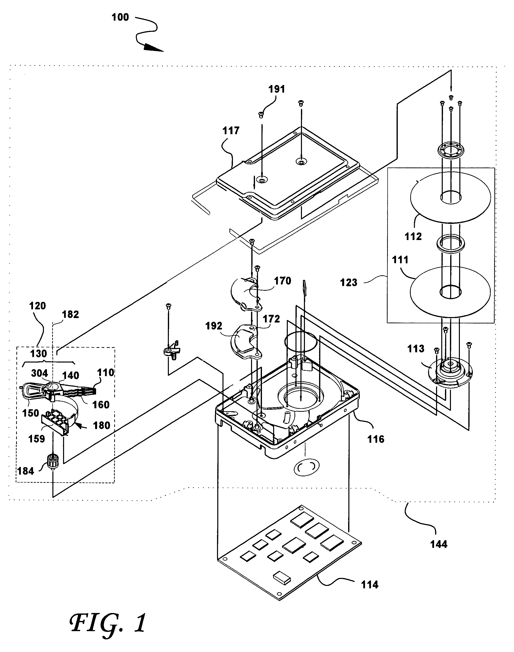
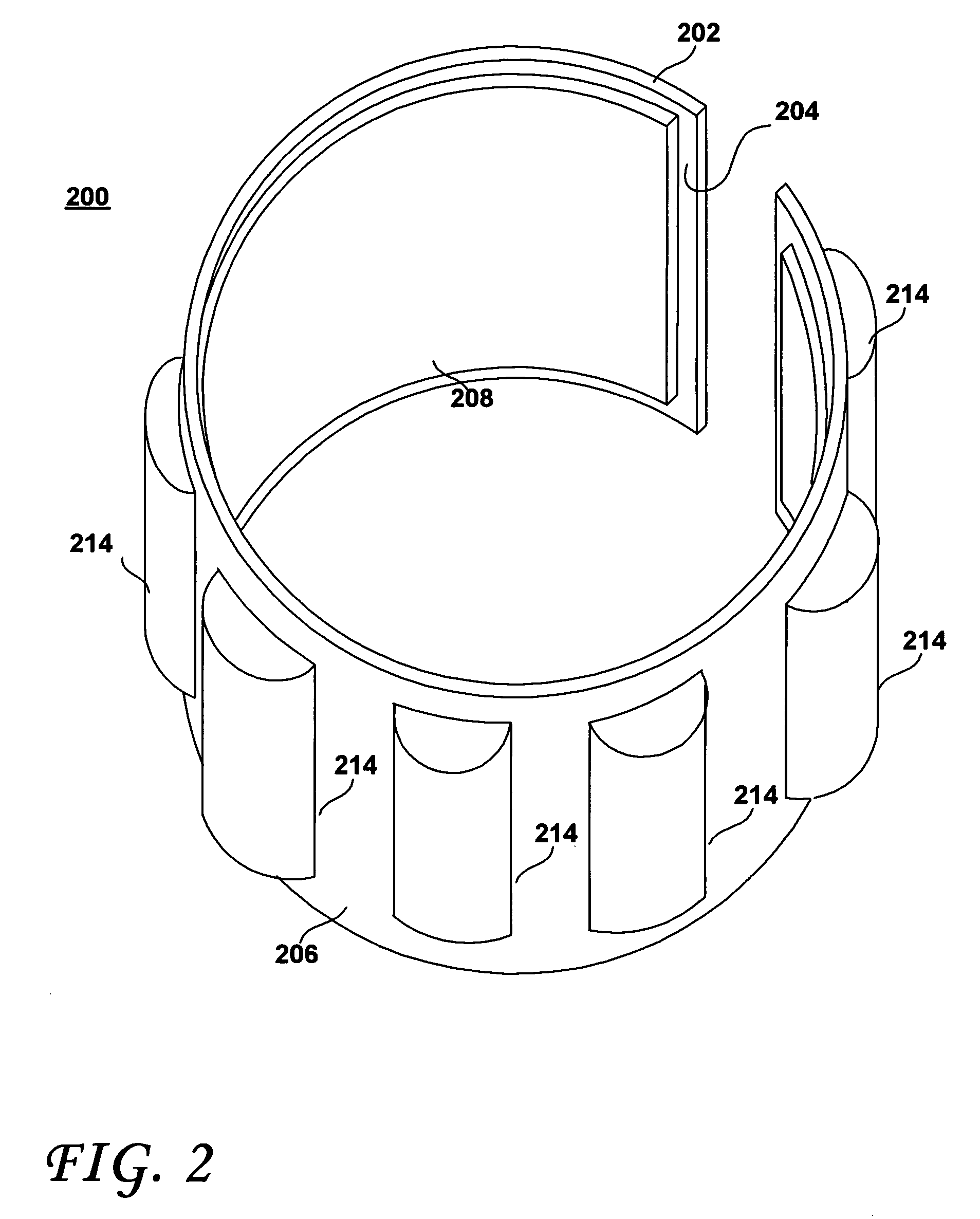
[0020]FIG. 1 shows the principal components of a magnetic disk drive 100 constructed in accordance with the present invention. With reference to FIG. 1, the disk drive 100 comprises a HDA 144 and a PCBA 114. The HDA 144 includes a disk drive enclosure comprising base 116 and a cover 117 attached to the base 116 that collectively house a disk stack 123 that includes one or a plurality of magnetic disks (of which only a first disk 111 and a second disk 112 are shown), a spindle motor 113 attached to the base 116 for rotating the disk stack 123, an HSA 120, and a pivot-bearing cartridge 184 that rotatably supports the HSA 120 on the base 116. The spindle motor 113 rotates the disk stack 123 at a constant angular velocity. The HSA 120 comprises a swing-type or rotary actuator assembly 130, at least one HGA 110, and a flex circuit cable assembly 180. The rotary actuator assembly 130 includes a body portion 140, at least one actuator arm 160 cantilevered from the body portion 140, and a c...


PUM


Abstract

A disk drive includes a pivot-bearing cartridge configured to pivotally support the head stack assembly on the base of the drive. A tolerance ring is coupled to the pivot-bearing cartridge and includes a single sleeve defining an inner sleeve surface facing the pivot-bearing cartridge and an outer sleeve surface facing away therefrom, and a layer of dampening material disposed on the inner or outer sleeve surfaces so as to be in contact with the pivot-bearing cartridge or the bore surface of the through bore that is defined in the body portion of the head stack assembly, respectively.

Description

BACKGROUND OF THE INVENTION[0001]1. Field of the Invention[0002]This invention relates to head stack assemblies and to magnetic disk drives. In particular, the present invention relates to head stack assemblies and disk drives including a pivot-bearing cartridge including a damping layer to reduce vibrations in the actuator assembly.[0003]2. Description of the Prior Art and Related Information[0004]As the storage capacity of disk drives increases, the number of tracks per inch (TPI) on which data is stored also increases. As the TPI increases, the importance of the servo bandwidth controlling the head correspondingly increases. As the actuator is controlled to move ever faster, unwanted resonances occur that are detrimental to the operation of the drive. Such actuator resonances transfer to the suspension assembly to which the read / write heads are located, to the pivot-bearing cartridge, as well as to the base and the cover of the drive. Theses vibrations contribute to off-track mot...

Claims


Application Information

Patent Timeline
IPC IPC(8): G11B5/55G11B21/08G11B33/14
CPCG11B5/5526G11B5/4813
Inventor OVEYSSI, KAMRANLIN, CHEN-CHI
Owner WESTERN DIGITAL TECH INC
Why Eureka
Eureka Blog
Learn More