
Optical information reading apparatus

Inactive Publication Date: 2006-08-01
DENSO WAVE INC
View PDF11 Cites 40 Cited by
  • Summary
  • Abstract
  • Description
  • Claims
  • Application Information

AI Technical Summary

Benefits of technology

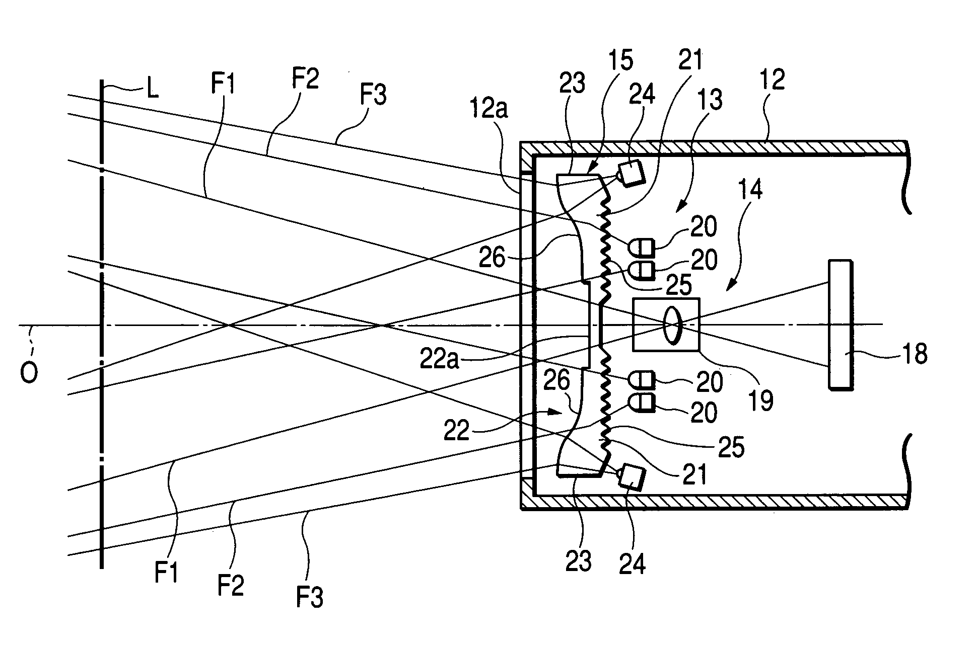
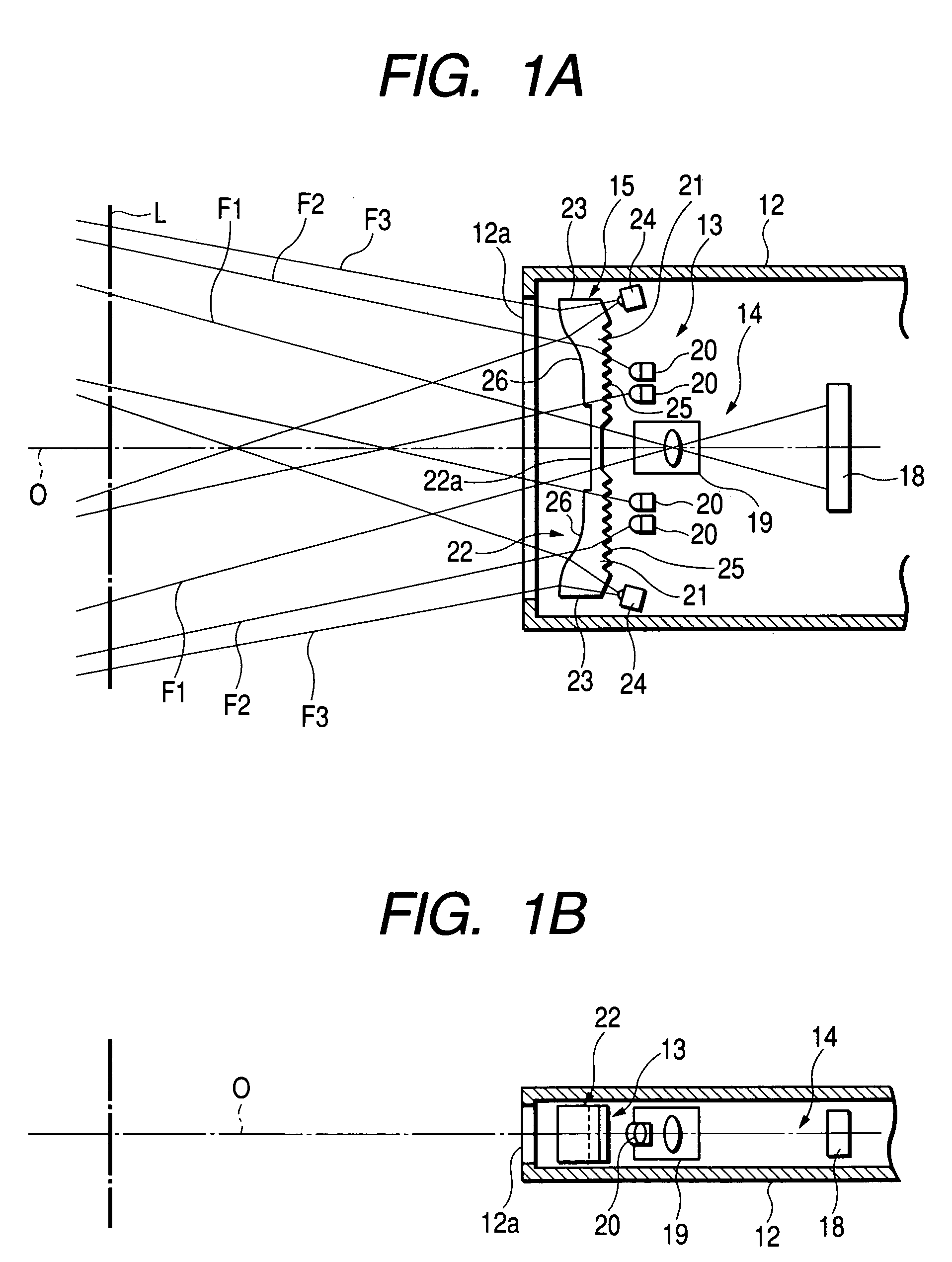
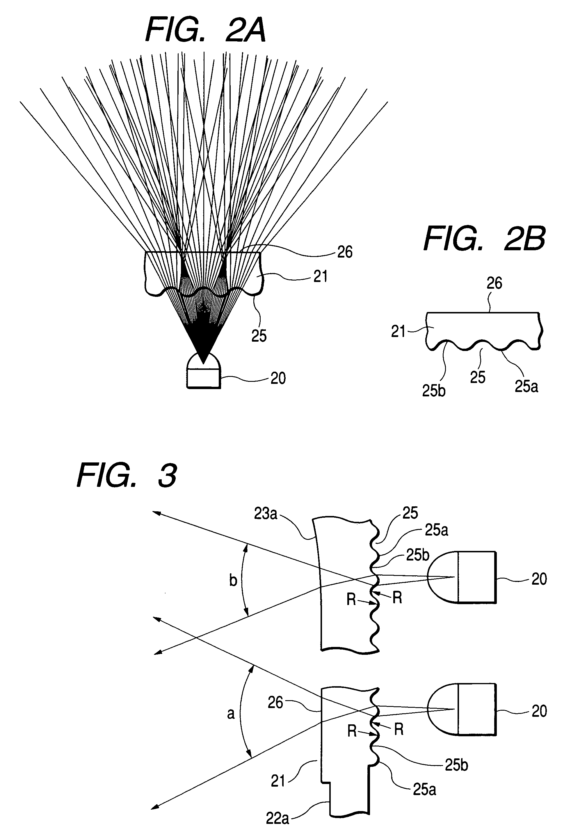
[0010]With this construction, in the illumination lens means, the multi-tiered lens unit can diffuse (spread) the light from an illumination light source uniformly in the read width directions and the rod-like lens unit can provide the illumination light which does not diffuse in directions perpendicular to the read width directions. At this time, since the multi-tiered lens unit includes the plurality of concave lens tiers and the plurality of convex lens tiers which are alternately disposed in succession, all the lights from the illumination light source can pass therethrough, which provides bright illumination light efficiently without waste. Moreover, since the illumination lens means is constructed in a state the multi-tiered lens unit and the rod-like lens unit are integrated with each other, the simplification of the construction is achievable as compared with separate construction, which contributes to the size reduction and weight reduction of the entire apparatus.
[0012]Meanwhile, the trend of the light reception in this type of optical information reading apparatus is that, due to the characteristic of the light-receiving optical system (image formation lens), a peripheral (fringe) portion in the read width directions becomes darker as compared with a central side portion (portion close to the center). Therefore, the illumination lens means is arranged such that the peripheral portion and central side portion in the read width direction differ in optical characteristic from each other so that the peripheral portion has a light diffusion range smaller than that of the central side portion. This makes the degree of condensing of the illumination light in the peripheral portion larger to compensate for the darkened peripheral portion stemming from the characteristic of the light-receiving optical system, thus enhancing the readability.
[0014]In addition, for indicating a read position, a guide optical system can be provided which includes a guide light source for emitting laser light and a guide lens for spreading the light emitted from the guide light source in the read width directions, and in the case of the employment of this guide optical system, the guide lens can be formed integrally with the illumination lens means. This simplifies the apparatus construction.
[0015]Still additionally, in a case in which two illumination optical systems each corresponding to the aforesaid illumination optical system are disposed symmetrically with respect to the light-receiving optical system, and the illumination lens means of the symmetrically disposed illumination optical systems are integrally connected to each other through a connection portion which does not function as a lens. Thus, because of the integration of the right- and left-side illumination lens means, the reduction of the number of parts and the improvement of the assembling performance are achievable.

Problems solved by technology

However, this lenticular lens 1 has inflection points 1b between convex lens tiers 1a, and light does not emerge at the inflection point 1b portions, which creates a problem in that the uselessness occurs in light quantity and difficulty is experienced in uniforming the illumination light.

Method used


Image

  • Optical information reading apparatus
  • Optical information reading apparatus
  • Optical information reading apparatus

Examples


first embodiment

(First Embodiment)

[0031]Referring to FIGS. 1A to 7, a description will be given hereinbelow of a first embodiment of the present invention. In this embodiment, the present invention is applied to a handy-type bar-code reader acting as an optical information reading apparatus.

[0032]A bar-code reader 11 serving as an optical information reading apparatus according to this embodiment is accommodated in a tip side of a vertically elongated case 12 with a size allowing it to be held and manipulated by one hand of a user as shown partially in FIG. 7 and, as shown in FIGS. 1A and 1B, is made up of an illumination optical system 13 forming an illumination means for reading a bar code recorded on an object L of reading such as a label (not shown), a light-receiving optical system 14 forming a light-receiving means and a guide optical system 15 forming a guide light illumination means. In a tip surface of this case 12, there is formed a read window (read opening) 12a having a horizontally elo...


PUM


Abstract

The present invention provides an optical information reading apparatus capable of producing uniform and bright illumination light and of projecting the illumination light onto an appropriate position on an object of reading at all times. In the apparatus, a light-receiving optical system including a light-receiving sensor and an image formation lens is provided and illumination optical systems each including an LED and an illumination lens device are placed on both sides of the image formation lens. The illumination optical systems are integrally connected to each other through a connecting portion to form a lens-connected assembly. In an incident surface of the illumination lens device, a plurality of convex lens tiers and a plurality of concave lens tiers are alternately made smoothly to form a multi-tiered lens surface, and an output surface thereof is made into a gentle cylindrical configuration to form a rod-like lens surface.

Description

BACKGROUND OF THE INVENTION[0001]1) Field of the Invention[0002]The present invention relates to an optical information reading apparatus designed to read information codes such as bar codes.[0003]2) Description of the Related Art[0004]This type of conventional optical information reading apparatus (bar code reader) is made by accommodating, in a case, an illumination optical system including a plurality of LEDs and illumination lenses located in front thereof, and a light-receiving optical system including image formation lenses and light receiving sensors. The illumination optical system emits illumination light with a horizontally elongated configuration through a read opening onto an object of reading (object to be read) such as bar-code printed paper (label), and the light-receiving optical system receives the reflected light from the object of reading to read the bar codes.[0005]In this case, so far, as the illumination lens there has commonly been employed a semicylindrical l...

Claims


Application Information

Patent Timeline
IPC IPC(8): G06K7/10G02B3/00G06T1/00H04N1/04
CPCG06K7/10732
Inventor TOYAMA, HIROSHIOOSHIMA, TADAOITO, MAKOTO
Owner DENSO WAVE INC
Learn More