
Hand tool having an adjustable head

a technology of adjustable head and hand tools, which is applied in the field of hand tools, can solve the problems of high manufacturing cost, low yield of hand tools, and inconvenient operation of hand tools, and achieve the effects of economic manufacturing cost, simple structure and convenient operation

Active Publication Date: 2006-08-01
CHEN KUNG CHENG
View PDF6 Cites 38 Cited by
  • Summary
  • Abstract
  • Description
  • Claims
  • Application Information

AI Technical Summary

Benefits of technology

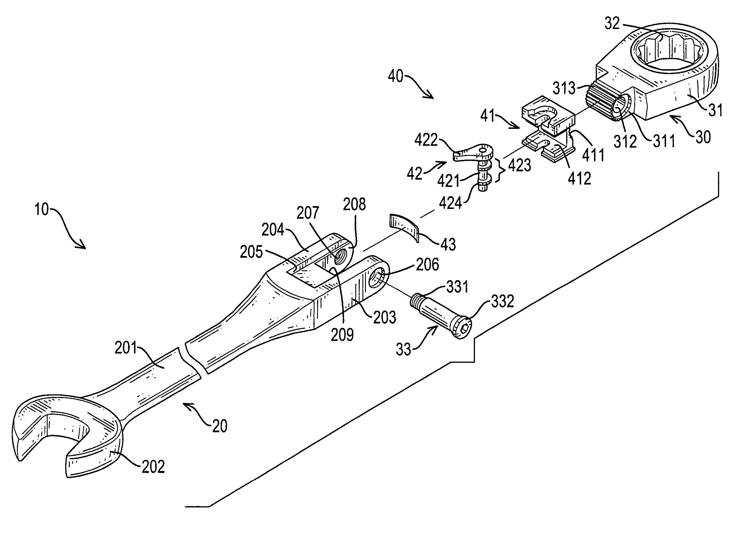
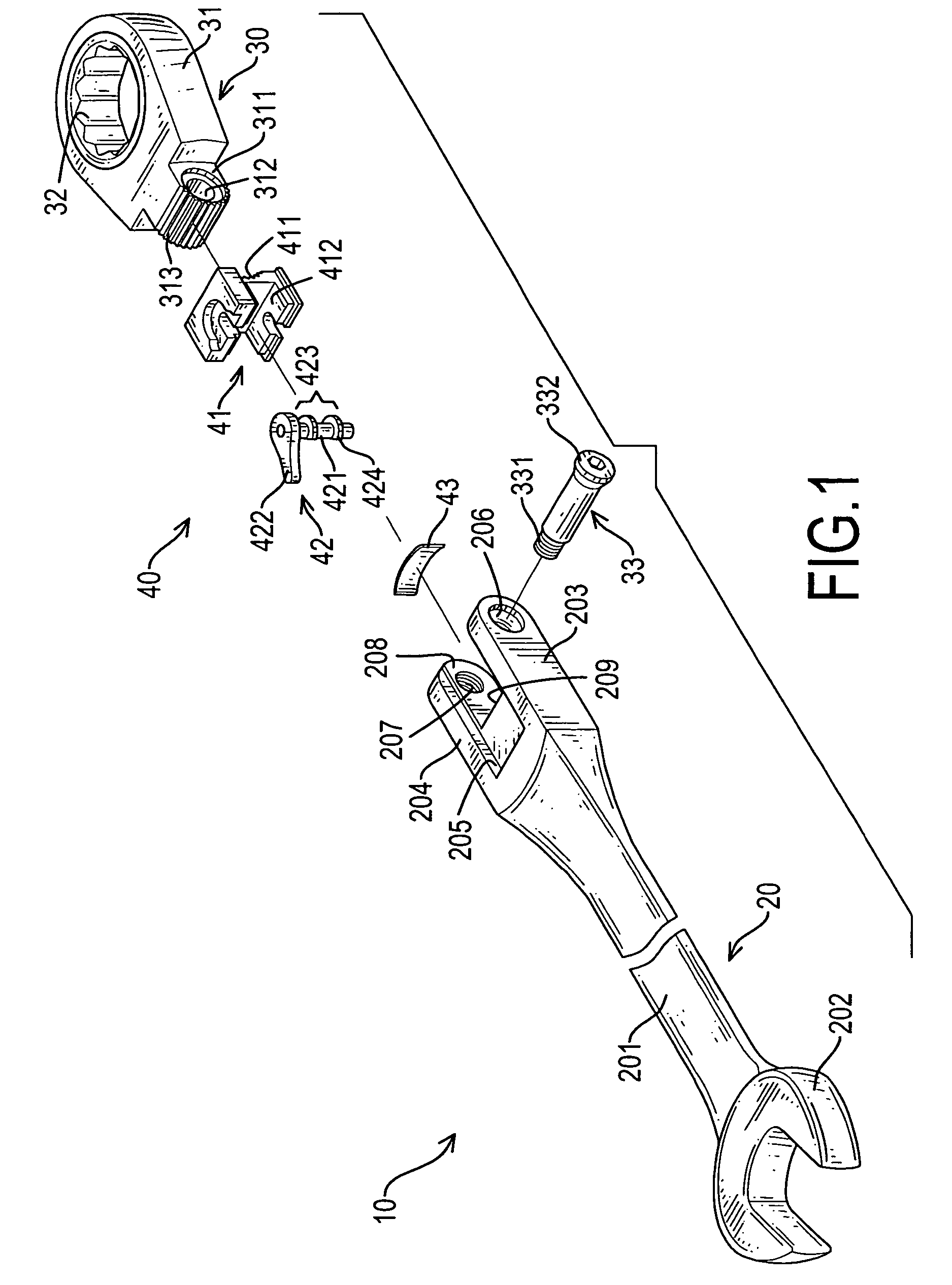
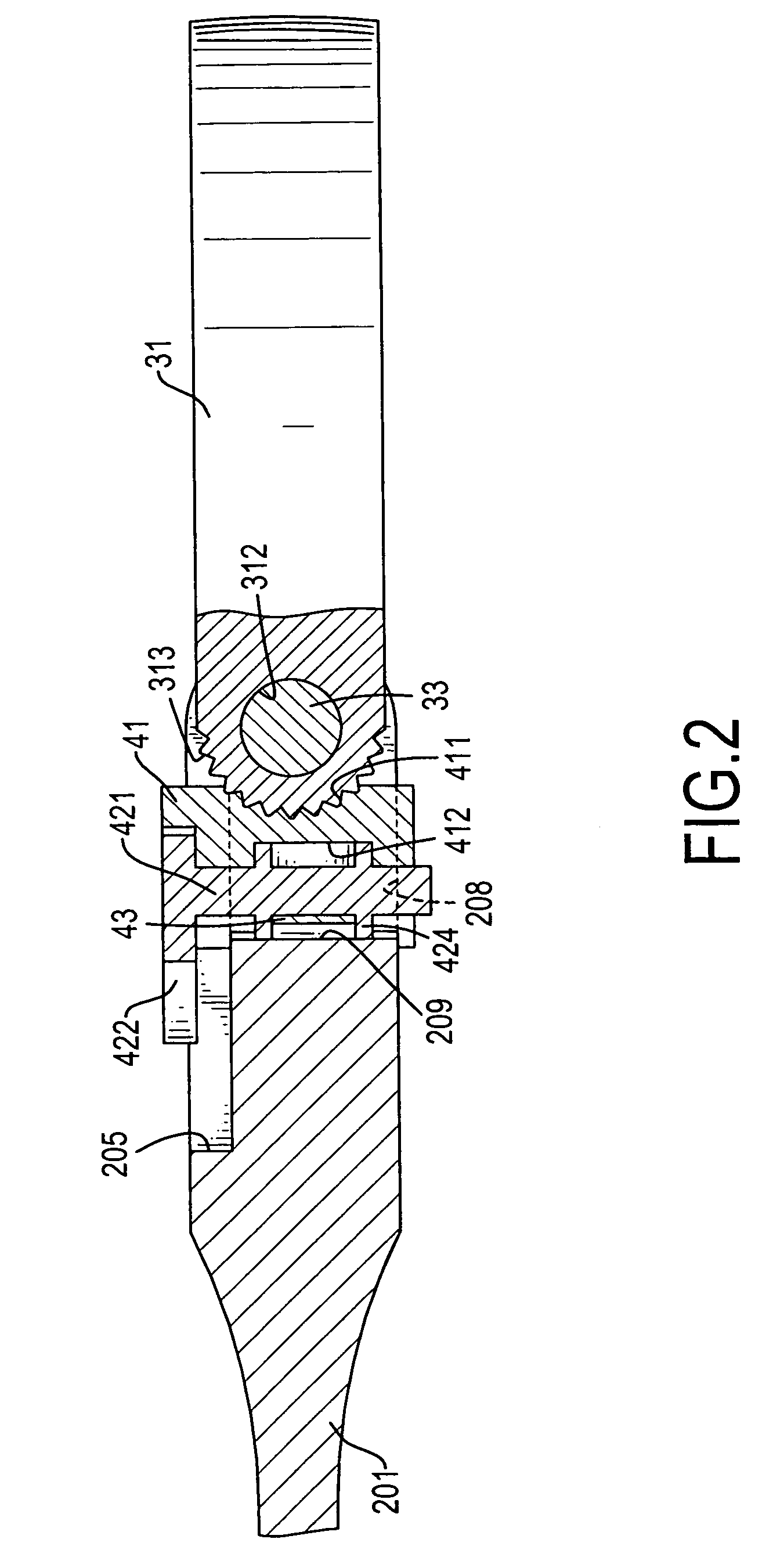
[0013]The main objective of the invention is to provide a hand tool with an adjustable head, and the ratchet hand tool has a simple structure and permits one-handed operations for adjusting the head to achieve convenience of operation and economic manufacturing costs.

Problems solved by technology

First, the conventional hand tools are neither easy nor quick to fabricate and assemble, especially assembling the head positioning device (66).
The handle (60) needs to have the positions of the holes (61, 63) precisely defined because if they are not manufacturing yields of the tools will be low and manufacturing costs will be excessive.
In addition, assembling the engaging ball (62), the inner spring (65) and the stepped rod (64) is inconvenient and slow.
Second, the head positioning device (66) of the conventional hand tools uses simply the engaging ball (62) to engage one detent (511), whereby the engaging effect between the engaging ball (62) and the detent (511) is weak and unreliable.
Third, since it is difficult to adjust the head (50) using only a single hand, the conventional hand tools are inconvenient to use.
Thus, one-handed operations for adjusting the head (50) of the conventional tools are difficult.

Method used


Image

  • Hand tool having an adjustable head
  • Hand tool having an adjustable head
  • Hand tool having an adjustable head

Examples


fourth embodiment

[0041]With reference to FIG. 7, the present invention modifies the third embodiment and implements the modification with the modified engaging device (411′) of the second embodiment. Since the descriptions of the functions and operations of the engaging device (411′) are provided in the aforesaid embodiments, a detailed description of the fourth embodiment is not provided.

[0042]With reference to FIGS. 8, 9 and 10, a fifth embodiment of the present invention is an alternative modification of the first embodiment and the modification is implemented with a modified rotatable locking assembly (42′) and a modified block biasing assembly (43″). The bottom (209) of the elongated slot (208) further has three detents: a first detent (210), a second detent (211) and a third detent (212). The second detent (211) is defined between the other two detents (210, 212).

[0043]The rotatable locking assembly (42′) comprises a spindle (421), a turning leaf (422) and a locking device such as an eccentric...


PUM


Abstract

A hand tool having an adjustable head includes a handle, a head and a head locking assembly. The handle has an elongated slot with a bottom. The head has a body that has a pivot junction pivotally mounted in the elongated slot and having an exterior toothed surface. The head locking assembly includes a sliding block, a rotatable locking assembly and a block biasing assembly. The sliding block is slidably mounted in the elongated slot between the pivot junction and the bottom of the elongated slot and includes an engaging device to engage the exterior toothed surface of the pivot junction. The rotatable locking assembly is rotatably mounted in the sliding block and includes a locking device such as an eccentric cam to abut the bottom of the elongated slot to restrict the sliding block in motion and lock the head at a given angular position.

Description

BACKGROUND OF THE INVENTION[0001]1. Field of the Invention[0002]The present invention relates to a hand tool, and more particularly to a ratchet hand tool with an adjustable head that utilizes a sliding block to position and lock the adjustable head at a given angle.[0003]2. Description of Related Art[0004]Hand tools, especially for ratchet socket wrenches are extensively used to tighten or loosen fasteners. With reference to FIG. 11, a conventional ratchet socket wrench in accordance with prior art comprises a head (50), a handle (60), a pivot pin (512) and a head positioning device (66). The head (50) is adjustably mounted on the handle (60) with the head positioning device (66) and comprises a head body (51) and a socket ratchet drive (52). The head body (51) is pivotally mounted on the handle (60) with the pivot pin (512) and has multiple detents (511) formed and arranged about the pivot pin (512). The socket ratchet drive (52) is mounted in the head body (51). The handle (60) h...

Claims


Application Information

Patent Timeline
Patent Type & Authority Patents(United States)
IPC IPC(8): B25B23/16B25B13/46B25B23/00B25G1/06
CPCB25G1/063B25B13/461
Inventor LEE, LI-JU
Owner CHEN KUNG CHENG
Learn More