Method and apparatus using traction seal fluid displacement device for pumping wells

a technology of fluid displacement and traction seal, which is applied in the direction of fluid removal, sealing/packing, and wellbore/well accessories, etc., can solve the problems of parts that wear and ultimately fail, present certain irregularities, and are susceptible to wear and failure, so as to reduce the energy cost of pumping, reduce the pumping efficiency, and eliminate or reduce wear.

Inactive Publication Date: 2006-07-25
FORESTAR PETROLEUM
View PDF53 Cites 5 Cited by
  • Summary
  • Abstract
  • Description
  • Claims
  • Application Information

AI Technical Summary

Benefits of technology

[0009]The present invention makes use of a rolling traction seal fluid displacement device located within a production tubing of a hydrocarbons-producing well to lift liquid up the production tubing and out of the well. The traction seal device is preferably moved up the production tubing by gas at a pressure and volume supplied by the earth formation, thereby significantly reducing the energy costs for pumping the well as a result of using natural energy sources either exclusively or significantly to pump the well. The traction seal device obtains traction against the production tubing and moves with substantially frictionless contact within the production tubing, thereby substantially eliminating or reducing the wear and ultimately the failure created by relative movement-induced friction. The rolling tractive contact of the traction seal device with the production tubing establishes an essentially complete seal within the production tubing and with itself to prevent the liquid above and the gas pressure below the traction seal device from leaking past it and reducing the pumping efficiency. Further still, the traction seal device has an ability to achieve these desirable features while passing through segments of the production tubing that may be irregular in shape, corroded or eroded, or have grooves and small pits, contain buildup, or even change size slightly.

Problems solved by technology

In general, however, common disadvantages of all the pumps include a susceptibility to wear and failure as a result of frictional movement, particularly because small particles of sand and other earth materials within the liquid create an abrasive environment that causes the parts to wear and ultimately fail.
Moreover, the physical characteristics of the well itself may present certain irregularities which must be accommodated by the pump.
The moving parts of the piston wear out, particularly under the influence of sand grain particles carried by the liquids into the well.
The frictional wear on the parts diminish their usable lifetime and may increase the pumping costs due to frequent repairs.
This clearance dimension reduces the sealing effect necessary to hold the liquid in front of the plunger as it moves up the production tubing.
Diminished pumping efficiency occurs as a result.
Although gas pressure lifts avoid the problems of friction and wear resulting from using movable mechanical components, gas pressure lifts frequently require the use of many items of auxiliary equipment to control the application of the pressures within the well and also require significant equipment to create the large volumes of gas at the pressures required to lift the liquid.
At some point in the production lifetime of a well, the costs of operating and maintaining the pump are counterbalanced by the diminished amount of hydrocarbons produced by the continually-diminishing formation pressure.
For deeper wells, more cost is required to lift the liquid a greater distance to the earth surface.
For those wells which require frequent repair because of failed mechanical parts, the point of uneconomic operation is reached while producible amounts of hydrocarbons may still remain in the well.
For those deep and other wells which require significant energy expenditures to pump, the point of uneconomic operation may occur earlier in the life of a well.

Method used


Image

  • Method and apparatus using traction seal fluid displacement device for pumping wells
  • Method and apparatus using traction seal fluid displacement device for pumping wells
  • Method and apparatus using traction seal fluid displacement device for pumping wells

Examples


Embodiment Construction

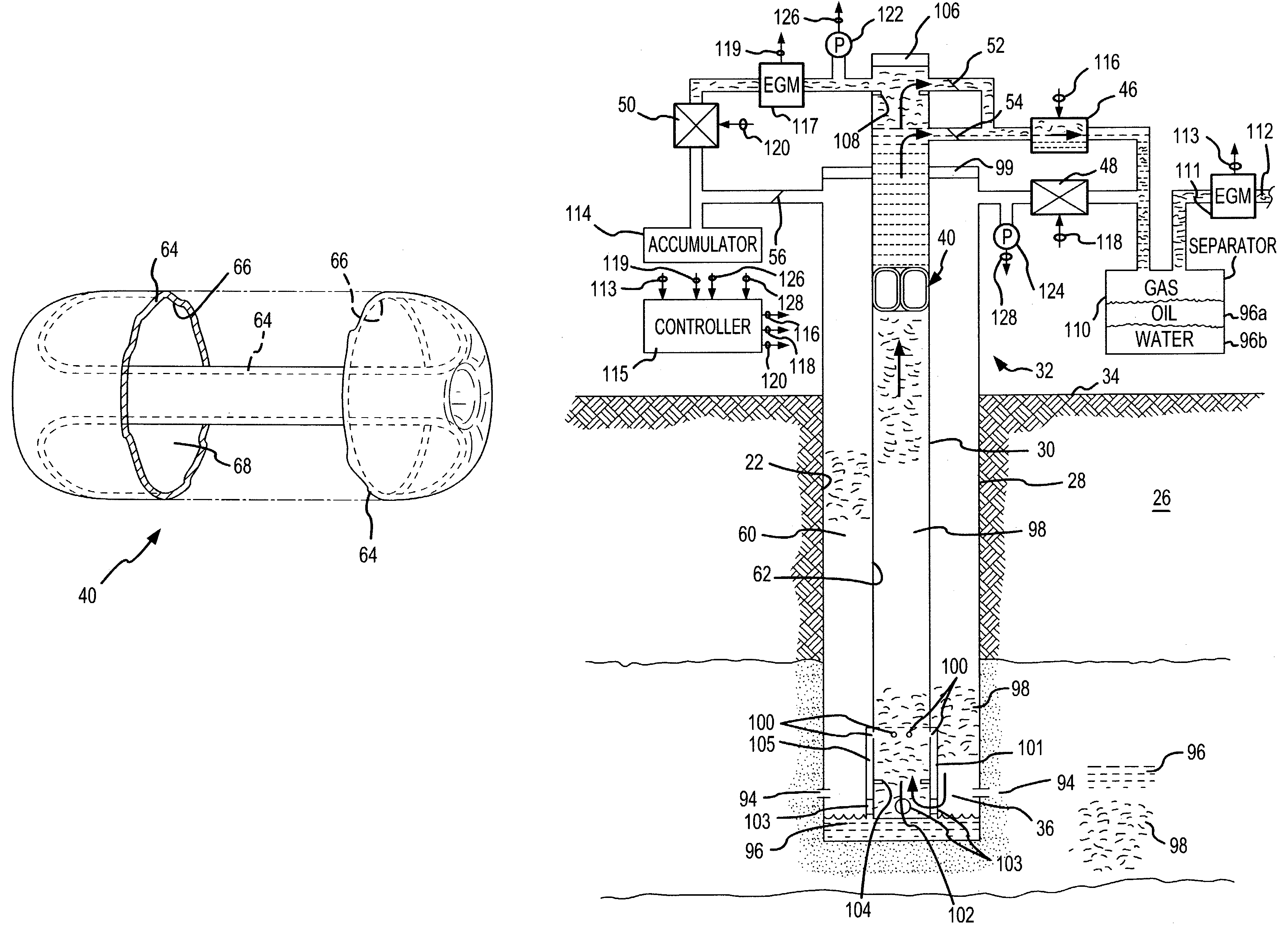
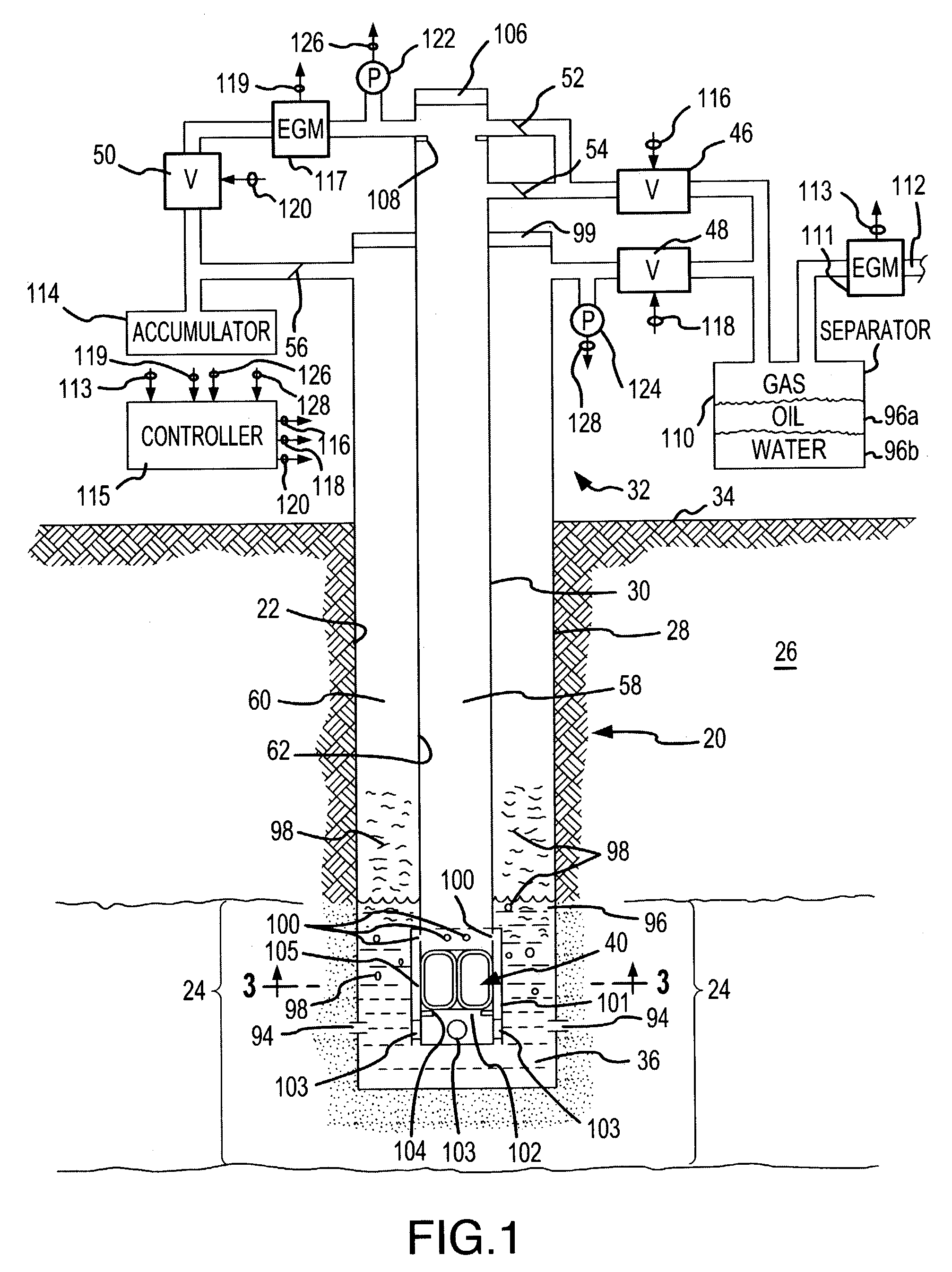
[0023]An exemplary hydrocarbons-producing well 20 in which the present invention is used the shown in FIG. 1. The well 20 is formed by a well bore 22 which has been drilled or otherwise formed downward to a sufficient depth to penetrate into a subterranean hydrocarbons-bearing formation or zone 24 of the earth 26. A conventional casing 28 lines the well 20, and a production tubing 30 extends within the casing 28. The casing 28 and the production tubing 30 extend from a well head 32 at the earth surface 34 to near a bottom 36 of the well bore 22 located in the hydrocarbons-bearing zone 24.

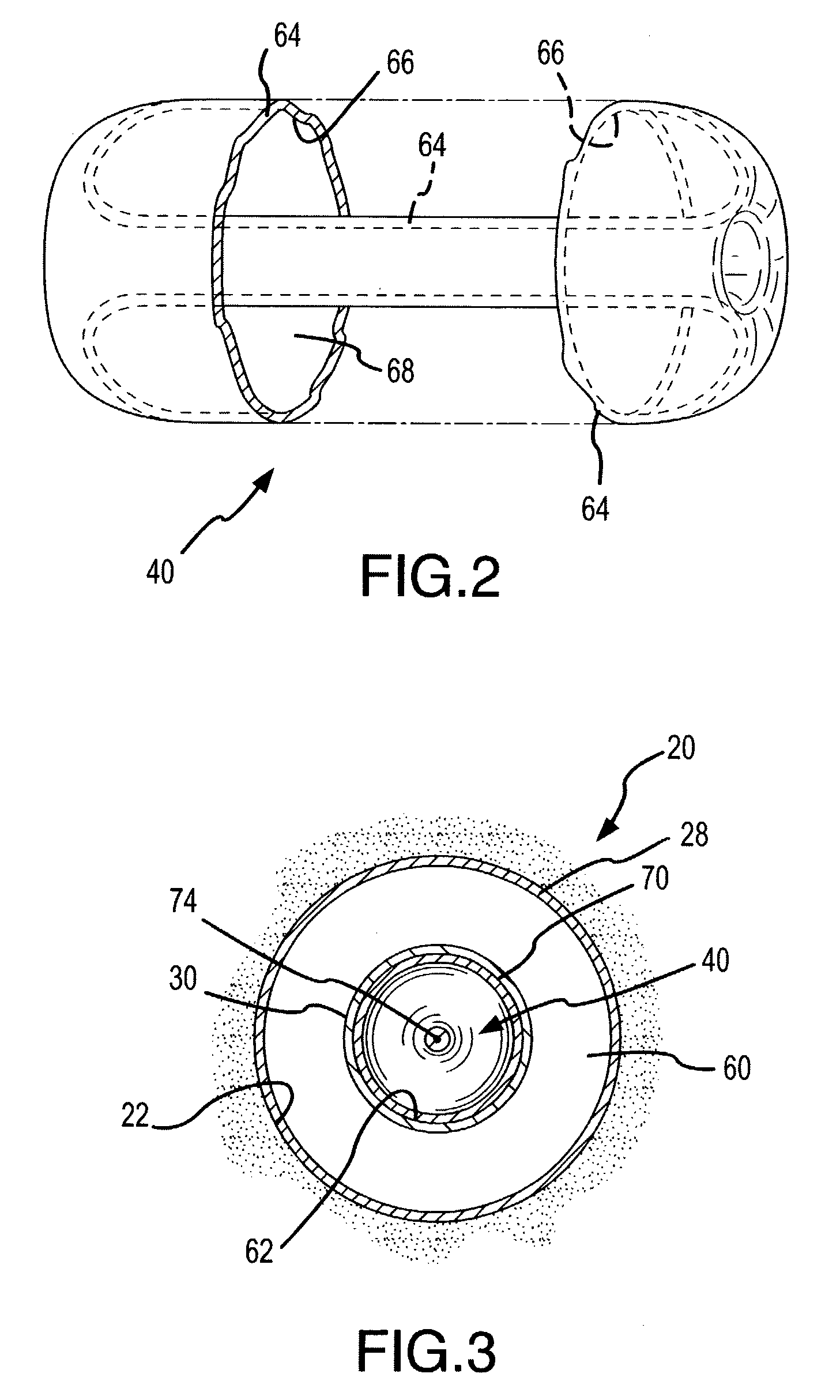
[0024]An endless rolling traction seal fluid displacement device 40 is positioned within the production tubing 30 and moves between the well bottom 36 and the well head 32 as a result of gas pressure applied within the production tubing 30. Formation pressure at the hydrocarbons-bearing zone 24 normally supplies the gas pressure for moving the traction seal device 40 up and down the production tubin...


PUM


Abstract

Liquid is lifted from a well by a traction seal fluid displacement device which is moveably positioned within the production tubing, and which maintains a seal during movement. The traction seal device comprises a resilient flexible toroid shaped structure within outside surface which contacts the inner sidewall of the production tubing and an inside surface which contacts itself to establish seals to these contact points as the outside surface rolls in essentially frictionless contact with in the production tubing. The toroid shaped structure is moved within the production chamber by applying a pressure differential across it. The pressure source is preferably natural gas at formation pressure.

Description

[0001]This invention relates to pumping fluids from a hydrocarbons-producing well formed in the earth. More particularly, the present invention relates to a new and improved method and apparatus that uses a rolling traction seal fluid displacement device, such as an endless, self-contained plastic fluid plug, in connection with gas pressures within the well to lift liquid from the well to thereby produce the hydrocarbons from the well.BACKGROUND OF THE INVENTION[0002]Hydrocarbons, principally oil and natural gas, are produced by drilling a well or borehole from the earth surface to a subterranean formation or zone which contains the hydrocarbons, and then flowing the hydrocarbons up the well to the earth surface. Natural formation pressure forces the hydrocarbons from the surrounding hydrocarbons-bearing zone into the well bore. Since water is usually present in most subterranean formations, water is also typically pushed into the well bore along with the hydrocarbons.[0003]In the e...

Claims


Application Information

Patent Timeline
Patent Type & Authority Patents(United States)
IPC IPC(8): E21B43/00E21B43/12
CPCE21B43/121
Inventor REITZ, DONALD D.
Owner FORESTAR PETROLEUM
Why Eureka
Try Eureka