
Temperature sensing circuit and method

a temperature sensing circuit and temperature technology, applied in the direction of pulse technique, semiconductor/solid-state device testing/measurement, instruments, etc., can solve the problem of not being able to sense the temperature in the semiconductor device with any greater accuracy

Active Publication Date: 2006-07-18
SAMSUNG ELECTRONICS CO LTD
View PDF8 Cites 58 Cited by
  • Summary
  • Abstract
  • Description
  • Claims
  • Application Information

AI Technical Summary

Benefits of technology

The invention provides a circuit and method for accurately sensing the temperature in a semiconductor device and digitizing the result. This allows for precise temperature monitoring in semiconductor devices.

Problems solved by technology

It cannot sense the temperature in the semiconductor device with any greater accuracy.

Method used


Image

  • Temperature sensing circuit and method
  • Temperature sensing circuit and method
  • Temperature sensing circuit and method

Examples


Embodiment Construction

[0026]Embodiments of the present invention will be described in detail with reference to the accompanying drawings. Like reference numerals refer to like elements throughout the figures.

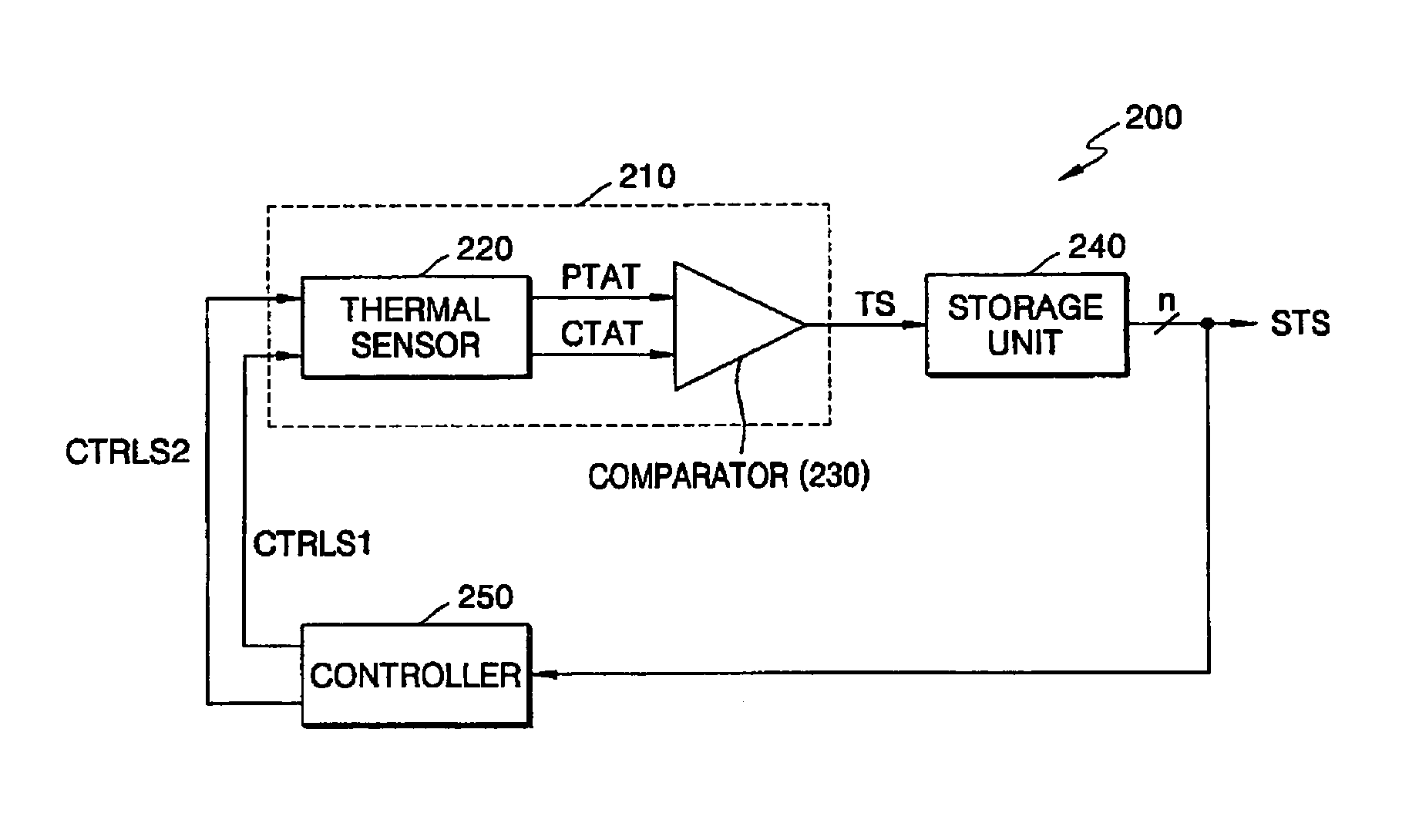
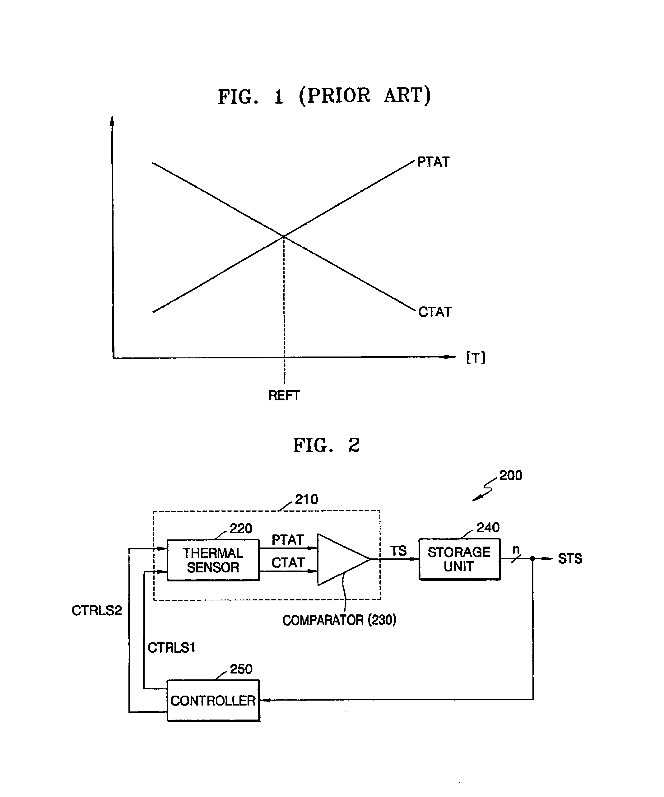
[0027]FIG. 2 is a block diagram illustrating a temperature sensing circuit according to an embodiment of the invention. Referring to FIG. 2, a temperature sensing circuit 200 includes a temperature sensing unit 210, a storage unit 240, and a controller 250.

[0028]The temperature sensing unit 210 outputs a temperature signal TS having information on whether the temperature in a semiconductor device is higher or lower than a reference temperature REFT in response to a first current control signal CTRLS 1 or a second current control signal CTRLS2. When the temperature rises, a first current level PTAT is increased and a second current level is CTAT reduced.

[0029]More specifically, the temperature sensing unit 210 includes a thermal sensor 220 and a comparator 230.

[0030]The thermal sensor 220 changes the ...


PUM

PropertyMeasurementUnit
operating temperatureaaaaaaaaaa
temperatureaaaaaaaaaa

Abstract

A temperature sensing circuit and method are provided. An example temperature sensing circuit includes a temperature sensing unit that outputs a temperature signal indicating whether the temperature in the semiconductor device is higher or lower than a reference temperature in response to a first current control signal or a second current control signal by using a first current level that is increased when the temperature rises and a second current level that is reduced when the temperature rises. The temperature sensing unit also includes a storage unit that stores and outputs the temperature signal, and a controller that changes the first current level or the second current level in response to the temperature signal output from the storage unit and generates the first current control signal or the second current control signal used to control the reference temperature.

Description

BACKGROUND OF THE INVENTION[0001]This application claims priority from Korean Patent Application No. 2003-45411, filed on Jul. 4, 2003, the disclosure of which is incorporated herein in its entirety by reference.[0002]1. Field of the Invention[0003]This disclosure relates to a temperature sensing circuit, and more particularly, to a temperature sensing circuit in which the temperature in a semiconductor device is sensed.[0004]2. Description of the Related Art[0005]A conventional thermal sensor senses the temperature in a semiconductor device and outputs the sensed result only as a ‘high’ or ‘low’ level.[0006]For example, a thermal sensor designed to sense a predetermined reference temperature outputs a ‘high’ level when a present temperature in a semiconductor device is higher than the predetermined reference temperature, and outputs a ‘low’ level when the present temperature in the semiconductor device is lower than the predetermined reference temperature.[0007]Thus, in order to se...

Claims


Application Information

Patent Timeline
Patent Type & Authority Patents(United States)
IPC IPC(8): H01L35/00G01K7/01G01K7/00H01L21/66H10N10/00H03K17/08
CPCG01K7/01H03K2017/0806H01L22/00
Inventor KIM, KWANG-HYUNKIM, CHAN-KYUNG
Owner SAMSUNG ELECTRONICS CO LTD
Learn More