
Instrument for separating ions in time as functions of preselected ion mobility and ion mass

a technology of ion mobility and ion mass, applied in the field of molecules characterization instruments, can solve the problems of labor-intensive manual and automated page techniques, limited accuracy of such systems, and inability to accurately detect the ion mass, etc., and achieve the effect of rapid analysis and sequencing

Inactive Publication Date: 2006-07-18
INDIANA UNIV RES & TECH CORP
View PDF20 Cites 31 Cited by
  • Summary
  • Abstract
  • Description
  • Claims
  • Application Information

AI Technical Summary

Benefits of technology

[0019]One object of the present invention is to provide instrumentation for rapid analysis and sequencing of large biomolecules, as well as analysis of mixtures of organic and inorganic molecules.

Problems solved by technology

However, both the manual and automated PAGE techniques suffer from several drawbacks.
For example, both approaches are labor-intensive since a gel must be prepared for each sequencing run.
Also, while automated PAGE systems may offer faster analysis times than a manual approach, the accuracy of such systems is limited by artifacts generated by non-uniform gel matrices and other factors.
Such automated systems are generally not equipped to accurately process the effects of such artifacts, which are typically manifested as “smiling” compressions, faint ghost bands, and the like.
Manual interpretation of such results is therefore often required which significantly increases analysis time.
While both large ion generating techniques are readily available, known MS techniques are limited in both the quantity and quality of discernable information.
However, such instruments are extremely expensive, not readily available, and because of their extremely high vacuum requirements, they are generally not suitable for routinely sequencing large numbers of samples.
However, due to the limited resolution of the mass spectrometer, ions are not completely separated in the spectrum, i.e. dots corresponding to different ions overlap.
While Guevremont et al. have had some experimental success in coupling an IMS instrument to a TOFMS instrument, their resulting instrumentation and techniques have several drawbacks associated therewith.
Secondly, because the drift tube and ion flight tube of the Guevremont et al. instrument are colinear, any spatial and temporal spread in an ion packet leaving the IMS leads directly to a spatial and temporal spread of ions in the ion acceleration region of the TOFMS.
These two characteristics lead to poor mass resolution in the TOFMS.
The combination of low resolution in the IMS and low resolution in the TOFMS makes this instrument incapable of resolving complex mixtures.

Method used


Image

  • Instrument for separating ions in time as functions of preselected ion mobility and ion mass
  • Instrument for separating ions in time as functions of preselected ion mobility and ion mass
  • Instrument for separating ions in time as functions of preselected ion mobility and ion mass

Examples


embodiment 30

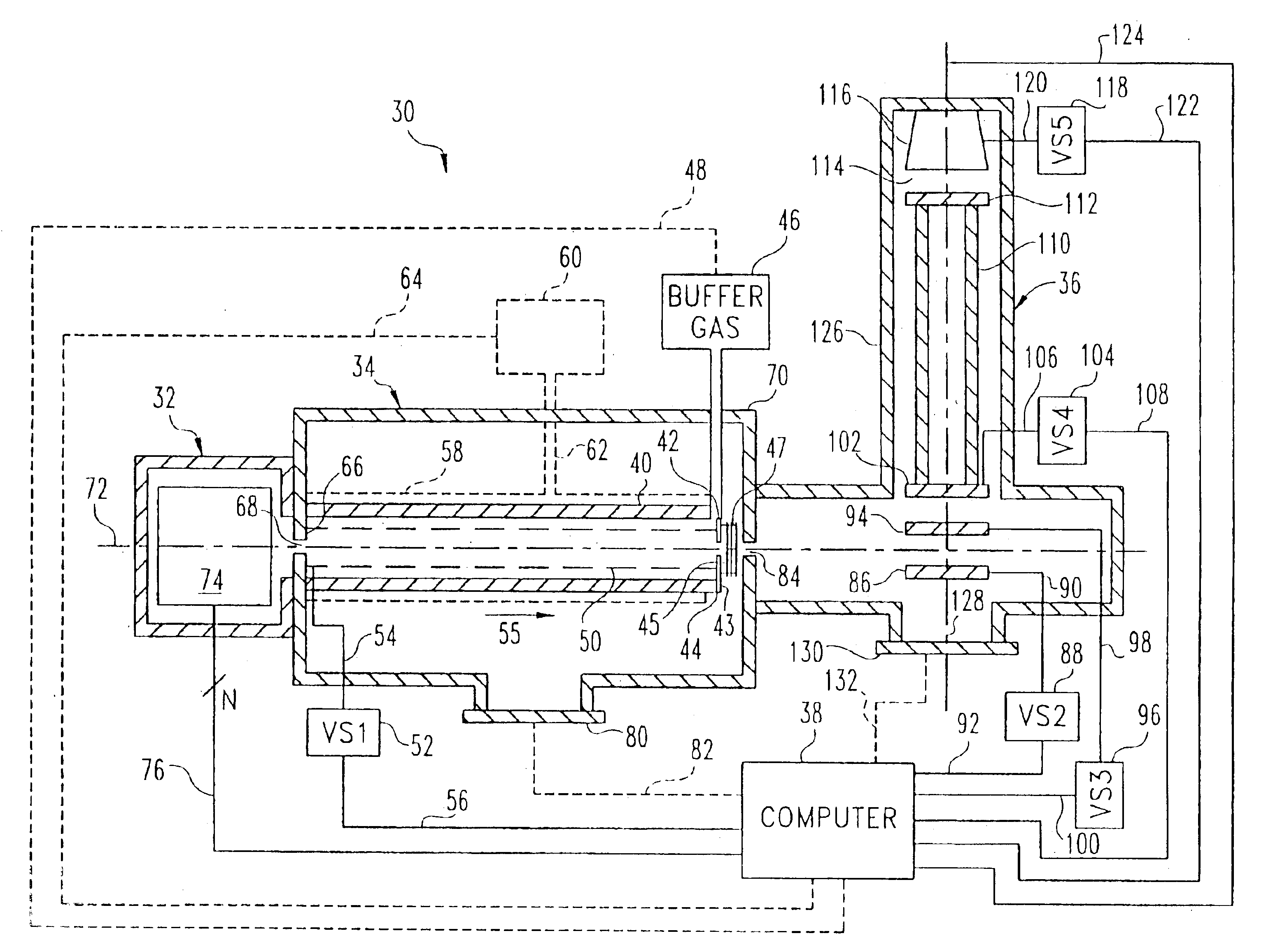
[0077]In order to address the foregoing problems associated with non-perpendicular positioning of the TOFMS 36′ relative to the IMS 34, which are the same problems associated with the Guevremont et al. system discussed hereinabove in the BACKGROUND section, instrument 150 is provided with an ion trap 152 operatively positioned between the ion outlet opening 84 of IMS 34 and the space defined between grids or plates 86′ and 94. In the embodiment illustrated in FIG. 5, grid or plate 86′ defines an ion inlet opening 178 therethrough which is aligned along axis 72 with ion outlet opening 84 of IMS 34. In other non-perpendicular arrangements of TOFMS 36′ relative to IMS 34, ion inlet opening 178 may not be required since ions may enter the space between grids or plates j86′ and 94 in the same manner as discussed with respect to the embodiment 30 illustrated in FIG. 4.

[0078]In any event, ion trap 152 is preferably a known quadrupole ion trap having a first endcap 154, a center ring 162 an...

embodiment 74

[0083]Referring now to FIG. 7A, one preferred embodiment 74′ of an ion source 74 for either of the instrument embodiments of FIGS. 4 and 5, is shown. Embodiment 74′ includes a chamber 200 having a sample 202 mounted therein and an optical window 206 extending therefrom. A radiation source 204 is electrically connected to computer 38 via signal path 76A, and is configured to direct radiation through optical window 206 to thereby irradiate sample 202. Chamber 200 may include a conduit extending therefrom to a pump 208 which may be controlled by computer 38 via signal path 76B.

[0084]Ion source 74′ is a known MALDI arrangement wherein radiation source 204, preferably a laser, is operable to desorb gaseous ions from a surface of the sample 202. Computer 38 is operable to control activation times of laser 204 to thereby control sample ionization events. The desorbed ions are directed by the internal structure of chamber 202 to ion inlet opening 68 of IMS 34. The sample 202 may, in accorda...


PUM

PropertyMeasurementUnit
flight timeaaaaaaaaaa
drift timeaaaaaaaaaa

Abstract

An ion separation instrument includes an ion source coupled to at least a first ion mobility spectrometer having an ion outlet coupled to a mass spectrometer. Instrumentation is further included to provide for passage to the mass spectrometer only ions defining a preselected ion mobility range. In one embodiment, the ion mobility spectrometer is provided with electronically controllable inlet and outlet gates, wherein a control circuit is operable to control actuation of the inlet and outlet gates as a function of ion drift time to thereby allow passage therethrough only of ions defining a mobility within the preselected ion mobility range. In another embodiment, an ion trap is disposed between the ion mobility spectrometer and mass spectrometer and is controlled in such a manner so as to collect a plurality of ions defining a mobility within the preselected ion mobility range prior to injection of such ions into the mass spectrometer. In yet another embodiment, an ion inlet of the ion trap may be electronically controlled relative to operation of the ion mobility spectrometer as a function of ion drift time to thereby allow passage therein only of ions defining a mobility within the preselected ion mobility range. The mass spectrometer is preferably a Fourier Transform Ion Cyclotron Resonance mass spectrometer, and the resulting ion separation instrument may further include therein various combinations of ion fragmentation, ion mass filtering, ion trap, charge neutralization and / or mass reaction instrumentation.

Description

CROSS REFERENCE TO RELATED APPLICATION[0001]This is a continuation of U.S. patent application Ser. No. 09 / 842,383, filed Apr. 25, 2001, and entitled INSTRUMENT FOR SEPARATING IONS IN TIME AS FUNCTIONS OF PRESELECTED ION MOBILITY AND ION MASS, which is a continuation-in-part of U.S. patent application Ser. No. 09 / 615,102, filed Jul. 13, 2000, now U.S. Pat. No. 6,498,342 entitled ION SEPARATION INSTRUMENT, which is a continuation-in-part of U.S. patent application Ser. No. 09 / 313,492, filed May 17, 1999, now U.S. Pat. No. 6,323,482 entitled ION MOBILITY AND MASS SPECTROMETER, which is a continuation-in-part of Ser. No. 08 / 867,245 filed Jun. 2, 1997 now U.S. Pat. No. 5,905,258 entitled HYBRID ION MOBILITY AND MASS SPECTROMETER.FIELD OF THE INVENTION[0002]The present invention relates generally to instrumentation for characterization of molecules based at least on their physical structures and mass-to-charge ratios as gas-phase ions, and more specifically to such instrumentation which p...

Claims


Application Information

Patent Timeline
Patent Type & Authority Patents(United States)
IPC IPC(8): H01J49/40G01N27/62G01N27/64H01J49/26H01J49/38
CPCG01N27/622H01J49/38H01J49/004G01N27/623
Inventor CLEMMER, DAVID E.
Owner INDIANA UNIV RES & TECH CORP
Learn More