
Cable manager

a cable manager and cable technology, applied in the field of cable managers, can solve the problems of time-consuming and troublesome steps, inability to work efficiently, and inability to fix the cable b>4/b> on the cable manager b>12/b>, so as to save time and resources, avoid waste of materials, and be assembled fast

Active Publication Date: 2006-07-18
PENG YUAN HUEI
View PDF42 Cites 58 Cited by
  • Summary
  • Abstract
  • Description
  • Claims
  • Application Information

AI Technical Summary

Benefits of technology

"The present invention provides a cable manager that saves time and resources, and is easy to assemble without wasting materials. The cable manager includes a body and a cable clamping device integrally formed on the body with a pair of clamping pieces forming a space and an opening. The space has a reception width and the opening has a smaller width. The body also has a fixing aperture for receiving a cable tie. The cable manager may also include a supporting portion to support the body. The cable manager is designed to be fast and efficient in saving time and resources."

Problems solved by technology

However, even though the conventional wiring device 1 is capable for firmly fixing the cable, the capability is useless.
Most importantly, the step of using the screw 4 to fix the cable 3 on the cable manager 12 is time consuming.
Therefore, it is clear that the step is very troublesome and time-consuming.
Furthermore, it is inconvenient to use the screw driver in a straight place.
Therefore, the above-mentioned disadvantages of the conventional wiring device needs to be resolved.

Method used


Image

  • Cable manager
  • Cable manager
  • Cable manager

Examples


Embodiment Construction

[0028]The present invention will now be described more specifically with reference to the following embodiments. It is to be noted that the following descriptions of preferred embodiments of the invention are presented herein for purpose of illustration and description only; it is not intended to be exhaustive or to be limited to the precise form disclosed.

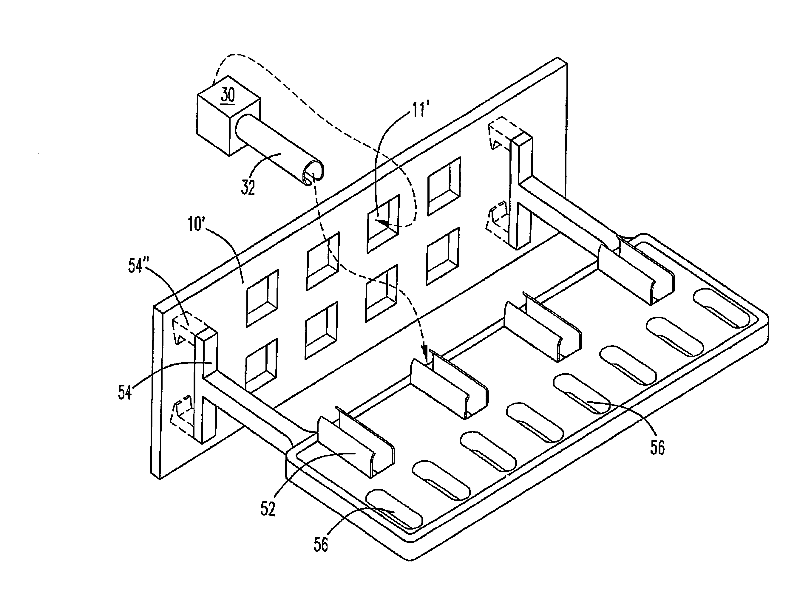
[0029]The present invention will now be described more specifically with reference to the following embodiments. Please refer to FIG. 2-1. FIG. 2-1 is a schematic view showing the cable manager according to a preferred embodiment of the present invention. The cable manager 5 includes a body 50. The body 50 has a cable clamping device 52 integrally formed on the body 50. The cable clamping device 52 has a pair of clamping pieces 520 forming a space 52″ and an opening 52′. The receiving direction of the opening 52′ is perpendicular to the surface of the cable manager 5. During the assembling, the wire portion 32 is directly pressed ...


PUM


Abstract

A cable manager includes a body and a cable clamping device integrally formed on the body. The cable clamping device has a pair of clamping pieces forming a space and an opening therein, and the space having a reception width and the opening having an opening width. The opening width is relatively smaller than the reception width.

Description

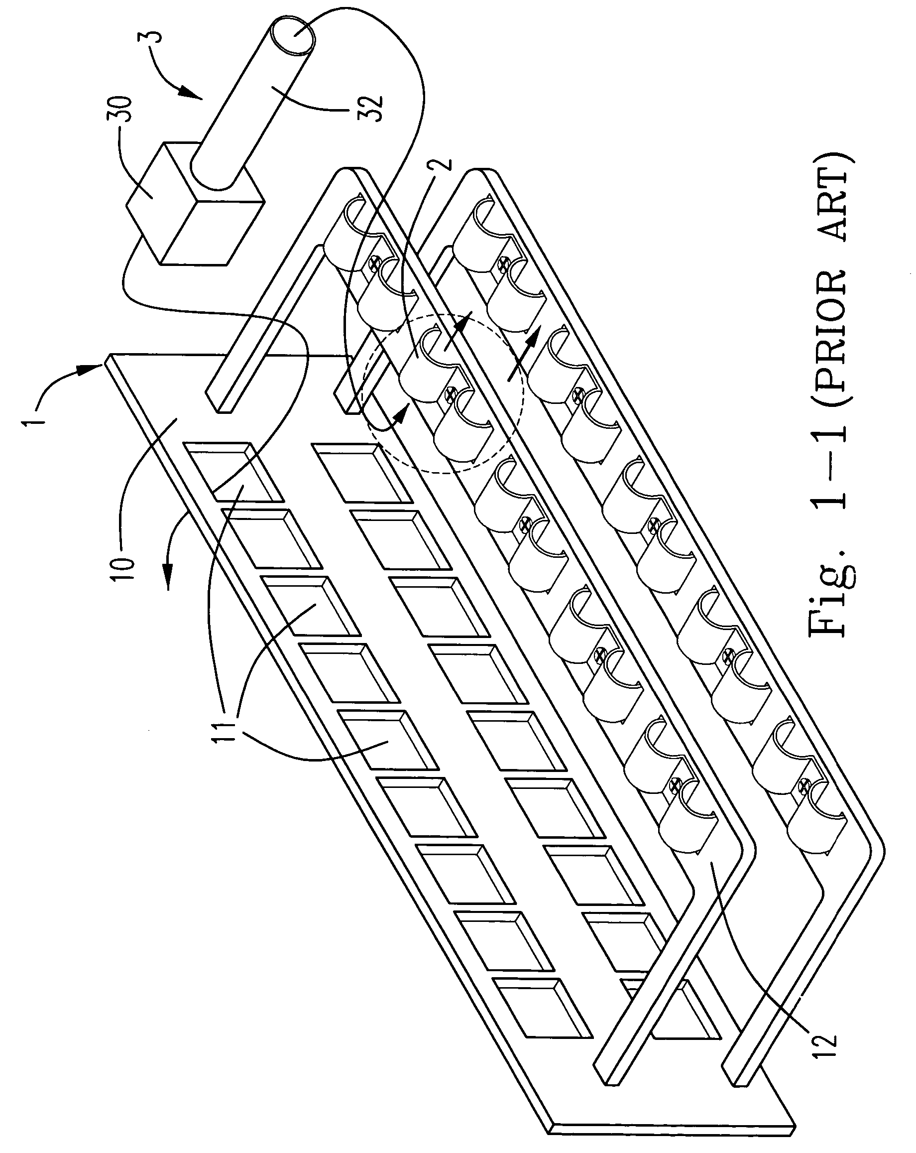
FIELD OF THE INVENTION[0001]The present invention is related to a cable manager, and more particularly, to a cable manager for use in internet wiring accessories.BACKGROUND OF THE INVENTION[0002]Please refer to FIG. 1-1. FIG. 1-1 is a schematic view showing a conventional wiring device. The wiring device 1 has a panel 10 including a plurality of wiring holes 11. The wiring device 1 further has a cable manager 12 extended therefrom and having plural clampers 2 for fixing a cable 3 on the cable manager 12. The clamper 2 clamps the wire portion 32 of the cable 3 and a connector 30 thereof is placed in the wiring hole 11.[0003]Please refer to FIG. 1-2. FIG. 1-2 is a sectional view of the conventional clamper. In FIG. 1-2, the clamper 2 is a very early design which is often made by metal, and has a pressing portion 22 at the laterals of the clamper 2. The pressing portion 22 presses the cable 3 on the cable manager 12 and a protrusion 24 is extended from an end of the pressing portion 22...

Claims


Application Information

Patent Timeline
Patent Type & Authority Patents(United States)
IPC IPC(8): H01R13/58H02G3/32
CPCH02G3/32
Inventor PENG, YUAN-HUEI
Owner PENG YUAN HUEI
Learn More