
Thin plate storage container with seal and cover fixing means

a technology of fixing means and storage containers, applied in the direction of containers, transportation and packaging, packaging goods, etc., can solve the problem of disadvantageous entry of contaminants into the container main body, and achieve the effect of preventing contaminan

Active Publication Date: 2006-07-18
MIRAIAL CO LTD
View PDF21 Cites 20 Cited by
  • Summary
  • Abstract
  • Description
  • Claims
  • Application Information

AI Technical Summary

Benefits of technology

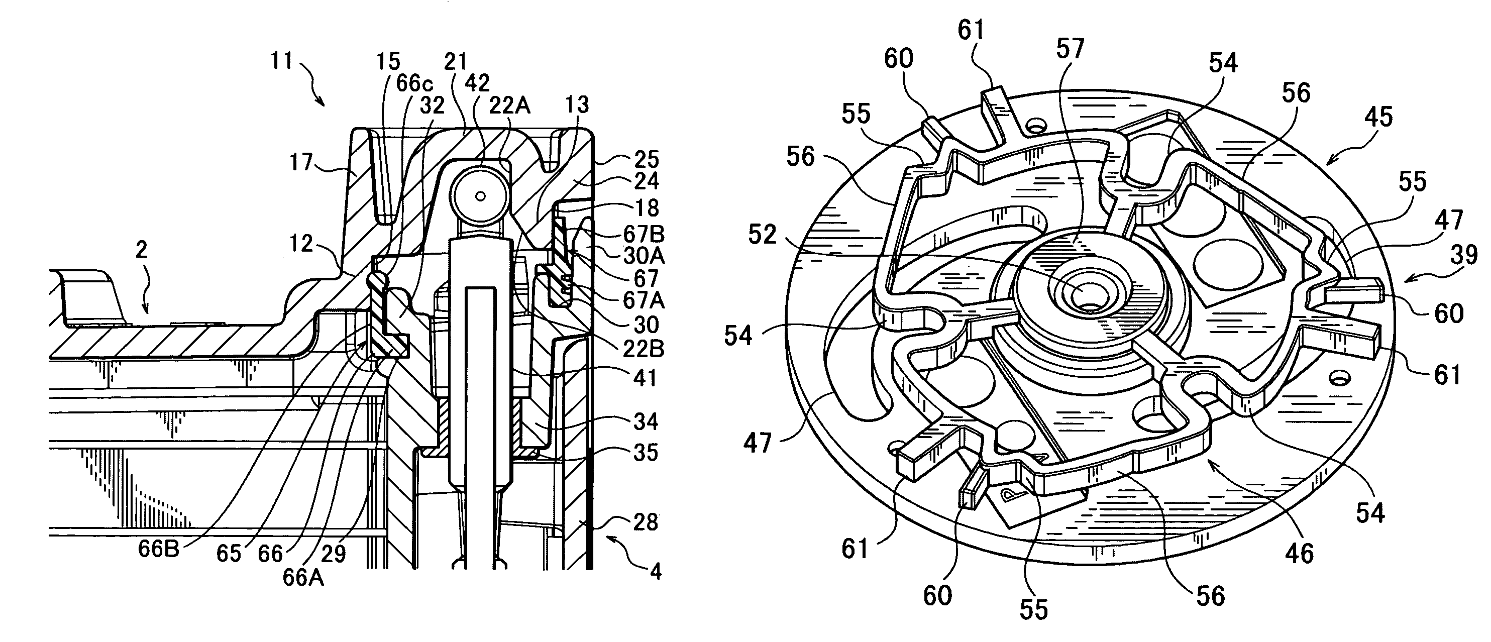
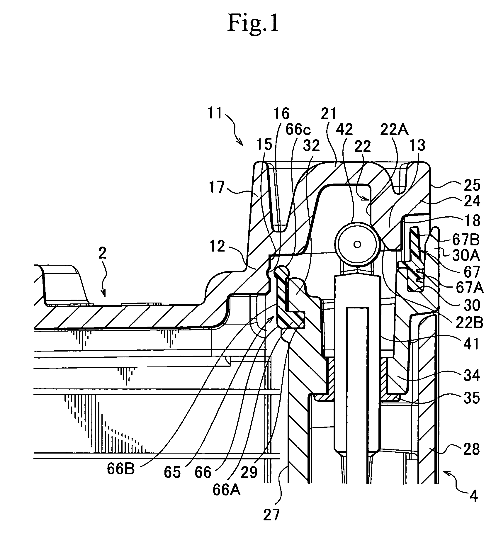
The present invention provides a thin plate storage container with improved sealability and detachability of the cover member. The container includes a container main body, a cover member, and a double-seal mechanism sealing the interior of the container main body. The double-seal mechanism consists of an inner seal piece and an outer seal piece that seals the interior and the abutment portion between the inner seal piece and the container main body. The inner seal piece is attached to the cover member and keeps the interior of the container clean. The outer seal piece prevents contaminants from entering the abutment portion. The cover member is attached to the container main body using a latch shaft and latch roller, and a cover member retracting surface is provided on the container main body to secure the cover member. The crank mechanism of the cover member fixing means includes a rotary plate and a support piece with engagement pins, and the engagement piece is projected and retracted by rotation of the rotary plate. The technical effects of the invention include improved sealability, detachability of the cover member, and prevention of contaminants from entering the container.

Problems solved by technology

However, when the cover member is detached from the container main body, a problem occurs.
If the contaminant enters the abutment portion between the sealant and the container main body, the contaminant disadvantageously enters the container main body.

Method used


Image

  • Thin plate storage container with seal and cover fixing means
  • Thin plate storage container with seal and cover fixing means
  • Thin plate storage container with seal and cover fixing means

Examples


Embodiment Construction

[0034]An embodiment of the present invention will be described hereinafter with reference to the accompanying drawings.

[0035]This embodiment will be described, while taking a semiconductor silicon wafer storage container for storing and transporting, as thin plates, semiconductor silicon wafers as an example.

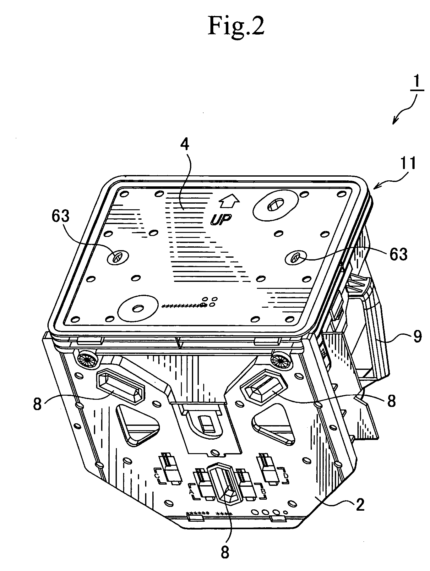
[0036]As shown in FIGS. 2, 3, and 12, the semiconductor silicon wafer storage container 1 includes a container main body 2 which stores and supports many semiconductor silicon wafers S inside, wafer support sections 3 which are provided on opposed sidewalls in the container main body 2, respectively, and each of which serves as a thin plate support section for holding the many semiconductor silicon wafers S contained in the container main body 2 one piece by one piece from both sides at certain intervals, and a cover member 4 which airtight closes an opening portion of the container main body 2 and which keeps an interior of the container 1 clean.

[0037]The entire container main ...


PUM


Abstract

A double-seal mechanism is provided on a cover member for sealing closed a container main body. The double-seal mechanism includes an inner seal piece that seals an interior of the container main body and is positioned between an inner seal reception section of a flange of the container main body and a seal pressing section of the cover. An outer seal piece forms a second seal between the container main body and the periphery of the cover member. The inner seal piece has a rounded distal end fitted into a fitting groove in the flange. A cover member fixing unit of the cover member includes a latch shaft that is linearly projected from and retracted, a latch roller attached to a tip end of the latch shaft, and a crank mechanism that linearly projects and retracts the latch shaft as the crank mechanism rotates. The latch roller travels along an inclined retracting surface on the container main body which forces the cover member inward into sealing engagement with the container main body.

Description

BACKGROUND OF THE INVENTION[0001]1. Field of the Invention[0002]The present invention relates to a thin film storage container which has an improved sealability for sealing a cover and a container main body and an improved detachability.[0003]2. Description of the Related Art[0004]Generally, there is known, as a thin film storage container, a container for storing and transporting semiconductor silicon wafers. As for the wafer storage and transport container, it is important to transport the container while keeping an interior of the container clean in order to prevent contamination of surfaces of the wafers contained therein. To this end, the interior of the container is sealed. That is, a cover member is fixed to a container main body, thereby sealing an interior of the container main body. The sealing of the cover member and the container main body is normally performed by providing a sealant between the cover member and the container main body. This sealant, which is attached to...

Claims


Application Information

Patent Timeline
Patent Type & Authority Patents(United States)
IPC IPC(8): B65D85/48B65D45/28B65D85/30
CPCH01L21/67376H01L21/67373
Inventor MATSUTORI, CHIAKI
Owner MIRAIAL CO LTD
Learn More