
Apparatus for exterminating an ant colony and method of using the same

a technology for destroying an ant colony and an ant food source, which is applied in the field of attracting and disabling an ant colony and the same, can solve the problems of destroying the colony and removing the food source of the ant colony, and achieve the effect of effectively removing an ant colony and quickly generating energy

Inactive Publication Date: 2006-07-18
MILLS COUNTY TECH
View PDF31 Cites 18 Cited by
  • Summary
  • Abstract
  • Description
  • Claims
  • Application Information

AI Technical Summary

Benefits of technology

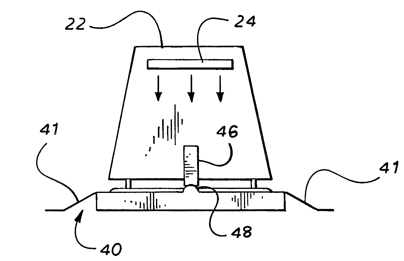
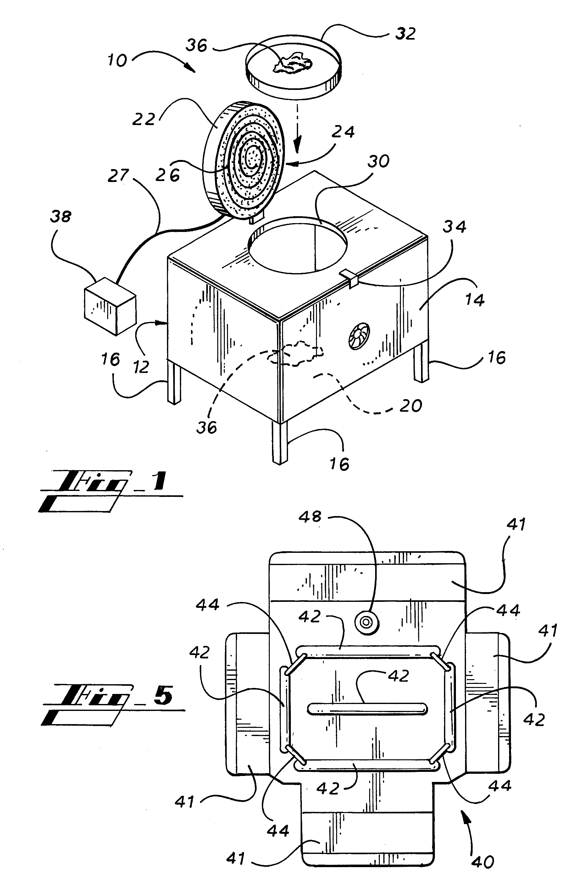
[0009]The ant exterminating apparatus further includes a cover that is pivotally attached to the uppermost surface of the side wall. The cover is able to pivot between an open position and a closed position. A heat or radiation producing element is affixed to the cover to quickly generate energy, such as heat, light or other radiation, within the housing upon command of either the user or a conventional timing device. Preferably, bait is placed proximate the housing to attract the worker ants, and the energy producing element is activated periodically. The energy producing element will raise the body temperature of the worker ants to such a degree that the worker ants will die while feeding on the bait or soon thereafter, thereby eliminating the food source for the ant colony, and consequently destroying the colony. A timer is additionally included in the apparatus for controlling the operation of the energy producing element.

Problems solved by technology

The energy producing element will raise the body temperature of the worker ants to such a degree that the worker ants will die while feeding on the bait or soon thereafter, thereby eliminating the food source for the ant colony, and consequently destroying the colony.

Method used


Image

  • Apparatus for exterminating an ant colony and method of using the same
  • Apparatus for exterminating an ant colony and method of using the same
  • Apparatus for exterminating an ant colony and method of using the same

Examples


Embodiment Construction

[0019]Looking now to FIG. 1, the ant exterminating apparatus 10 of the present invention is illustrated. This ant exterminating apparatus 10 includes a housing 12 or frame that is made of a fireproof material. The housing 12 of one embodiment includes a side wall 14 that surrounds a vacant area. The side wall 14 could be made of one continuous surface, or it may include any number of separate walls that are able to substantially surround a void area. The side wall 14 of the housing 12 is preferably supported above a ground surface by a series of legs 16. In addition to the side wall 14, the ant exterminating apparatus 10 may include an upper surface 18 connected to the upper edge of the side wall 14 and a lower surface 20 may be connected to the lower edge of the side wall 14.

[0020]Moreover, the ant exterminating apparatus 10 additionally includes a cover 22 that is pivotally attached to the uppermost surface of the side wall 14. The cover 22 is able to pivot between a closed positi...


PUM


Abstract

An ant exterminating apparatus operates to exterminate an ant colony using a energy producing element secured within a housing. The ant exterminating apparatus further includes a cover that is pivotally attached to a base plate. The cover is pivotable between an open position and a closed position, and an energy producing element is affixed to the cover to quickly generate radiation or heat energy between the cover and the base plate upon command of either the user or a conventional timing device. Bait is placed within the housing to attract the worker ants, and the energy producing element is activated periodically. The energy producing element will raise the body temperature of the ants such that the ants will die while feeding on the bait or soon thereafter, thereby destroying the colony.

Description

CLAIM OF PRIORITY[0001]The present patent application is a continuation-in-part patent application filed under 37 C.F.R. 1.53(b), claiming benefit from patent application Ser. No. 10 / 236,445, filed on Sep. 5, 2002 now abandoned, which further claims benefit from Provisional Application No. 60 / 317,075, filed on Sep. 5, 2001.FIELD OF THE INVENTION[0002]The present invention relates to an apparatus for attracting and disabling ants and other insects, and a method for using such an apparatus. More particularly, the present invention relates to an apparatus and use of such apparatus for attracting and disabling worker ants in a housing through the timed production of heat and radiation such that the ant colony is starved and thereby destroyed.BACKGROUND OF THE INVENTION[0003]Ants and similar insects are often considered to be common nuisances to people and animals alike. They live in a social organization wherein a series of castes of ants independently work on a specific job to maintain...

Claims


Application Information

Patent Timeline
IPC IPC(8): A01M1/00
CPCA01M1/02A01M1/2094A01M2200/011
Inventor BROOKS, SIDNEY DEWEYMILLER, ERIEABELO, ALAN
Owner MILLS COUNTY TECH
Learn More