Fraud detection through flow rate analysis
a flow rate analysis and fraud detection technology, applied in liquid/fluent solid measurement, liquid transfer devices, instruments, etc., can solve problems such as differences in fraudulent dispensers, fraud may be present, and more dispensers have been modified to produce fraudulent transactions
- Summary
- Abstract
- Description
- Claims
- Application Information
AI Technical Summary
Benefits of technology
Problems solved by technology
Method used
Image

Examples
second embodiment
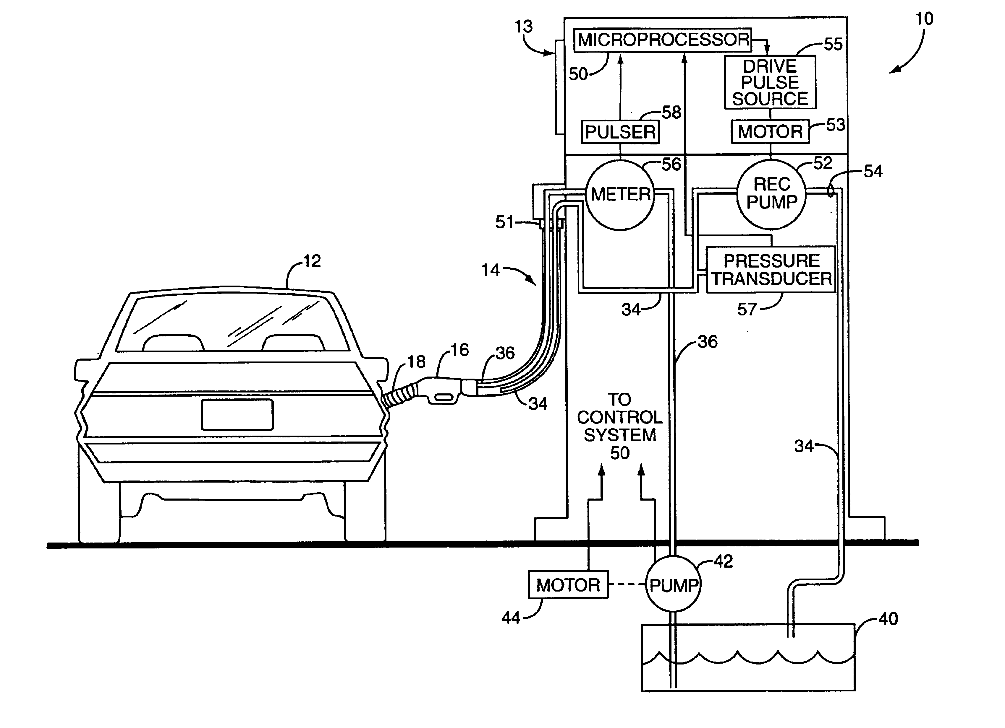
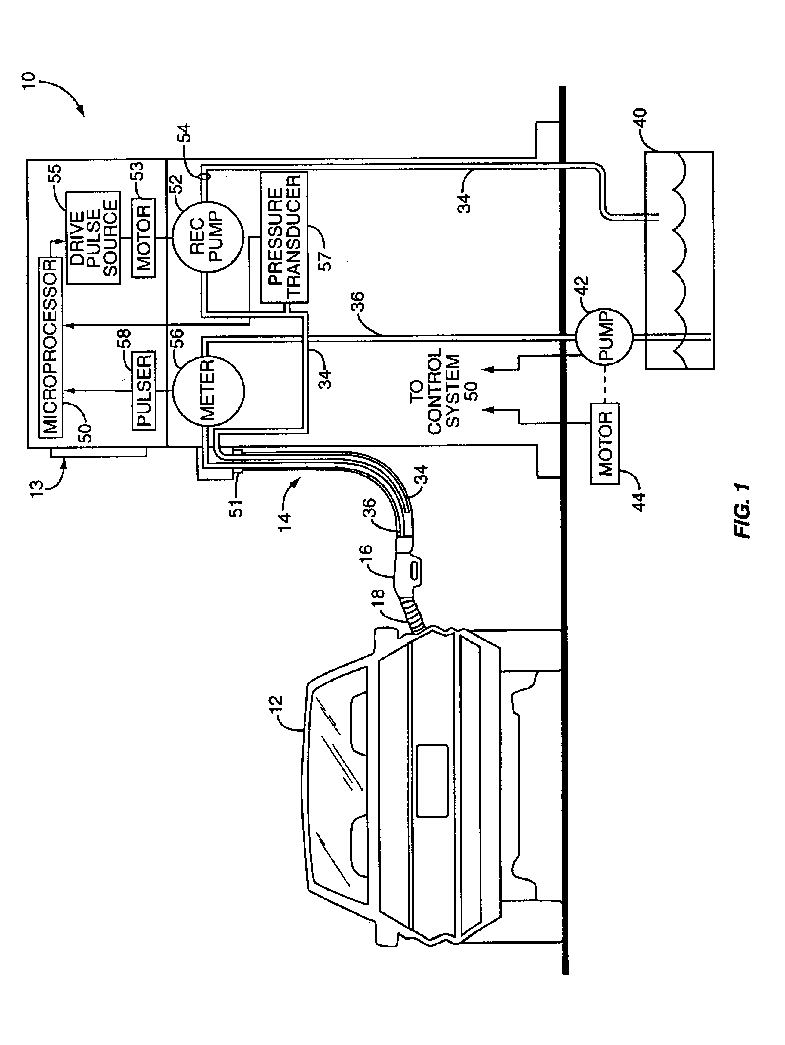
[0041]A second embodiment is seen in FIG. 5 wherein the flow rate of the fuel being dispensed is compared to an expected flow rate. If the pump 42 has been throttled back, and the pulser 58 providing inaccurate data to the control system 50, then the rate per gallon as reported by the pump 42 or motor 44 on average for non-fraudulent transactions should be significantly higher than the flow rate exhibited during fraudulent sales. For example, if a non-fraudulent fuel sale of ten gallons is delivered at an average of eight gallons per minute, a fraudulent fuel sale of eight gallons (but presented to the consumer as ten gallons) should exhibit a markedly lower average flow rate, perhaps six gallons per minute as reported by the pump42. If however, the pulser 58 has been accelerated without modification to pump 42, then the control system will show a flow rate that is much higher than the actual flow rate as well as one that appears faster than normal non-fraudulent sales. Additionally...
third embodiment
[0060]This third embodiment is essentially a modification of the average fueling rate embodiment in that a number of gallons delivered are being compared with a time required. However, the actual data that is being compared is slightly different—instead of an average fueling rate, two data points are being compared. The end result is the same, but the implementation may be different.
TANK MONITOR
fourth embodiment
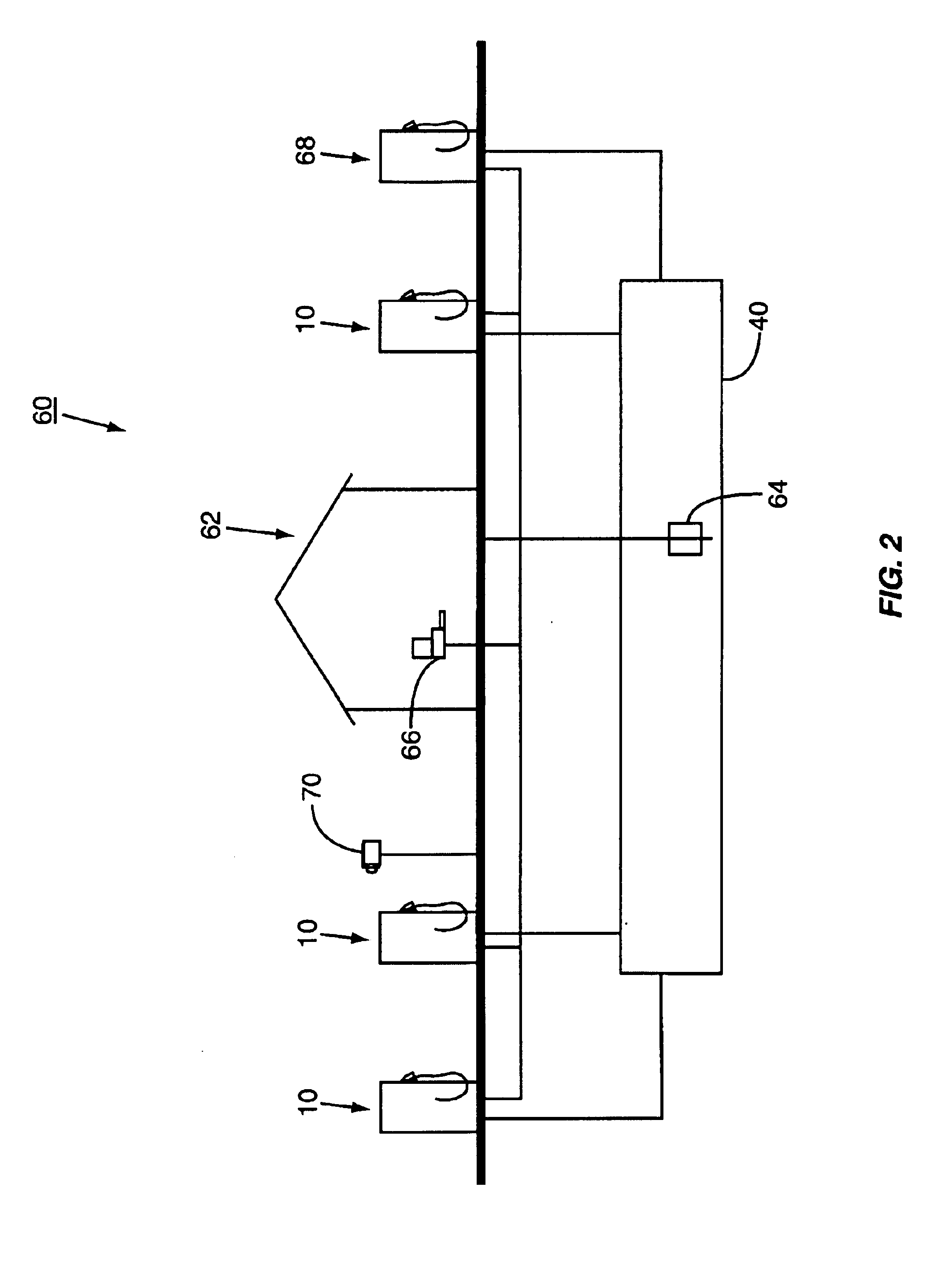
[0061]A fourth embodiment is seen in FIG. 7. This particular embodiment compares the amount of fuel that the fuel dispenser 10 indicates that it dispensed to the amount of fuel removed from the UST 40. Note that this embodiment functions best when only one fuel dispenser 10 is draining fuel from UST 40 at a time, and thus it may be difficult to isolate each dispenser 10 under such conditions. However, over a period of time, statistically, such isolated fueling events should occur, providing the fraud detection desired. Alternatively, the station owner / operator or the corporate fraud control agent can periodically perform the tests in controlled situations.
[0062]In a first aspect of this embodiment, the meter 56 and pulser 58 provide a measurement of the amount of fuel dispensed to the control system 50 (block 140). Sensor 64 measures the amount of fuel removed from the UST 40 (block 142) and provides this measurement to the control system 50. Control system 50 then compares the amou...
PUM
 Abstract
Description
Claims
Application Information
 - R&D
- Intellectual Property
- Life Sciences
- Materials
- Tech Scout
- Unparalleled Data Quality
- Higher Quality Content
- 60% Fewer Hallucinations
Browse by: Latest US Patents, China's latest patents, Technical Efficacy Thesaurus, Application Domain, Technology Topic, Popular Technical Reports.
© 2025 PatSnap. All rights reserved.Legal|Privacy policy|Modern Slavery Act Transparency Statement|Sitemap|About US| Contact US: help@patsnap.com