
Packet protection technique

a packet protection and packet technology, applied in data switching networks, frequency-division multiplexes, instruments, etc., can solve the problems of reducing the efficiency of the link bandwidth, difficult to put it in practical use, and taking a long time to restore, so as to reduce the efficiency of the network bandwidth and speed up the restoration

Inactive Publication Date: 2006-07-11
NEC CORP
View PDF15 Cites 23 Cited by
  • Summary
  • Abstract
  • Description
  • Claims
  • Application Information

AI Technical Summary

Benefits of technology

[0009]An object of the present invention is to provide a packet protection method and system which can achieve rapid restoration in case of fault occurrence without undesired reduction in efficiency on the use of network bandwidth.

Problems solved by technology

Accordingly, it will take much longer until restoration.
It is difficult to put it in practical use especially in the field of real-time data transmission such as voice and video data transmission.
However, all information are transferred through both working and protection line independently of its degree of importance, resulting in reduced efficiency on the use of the link bandwidth.
However, the duplicate important packets flow through the network at all times. Therefore, the greater the amount of important information, the greater the amount of packet flow to be protected.
This causes the efficiency on the use of the network bandwidth to be reduced.

Method used


Image

  • Packet protection technique
  • Packet protection technique
  • Packet protection technique

Examples


Embodiment Construction

SYSTEM CONFIGURATION

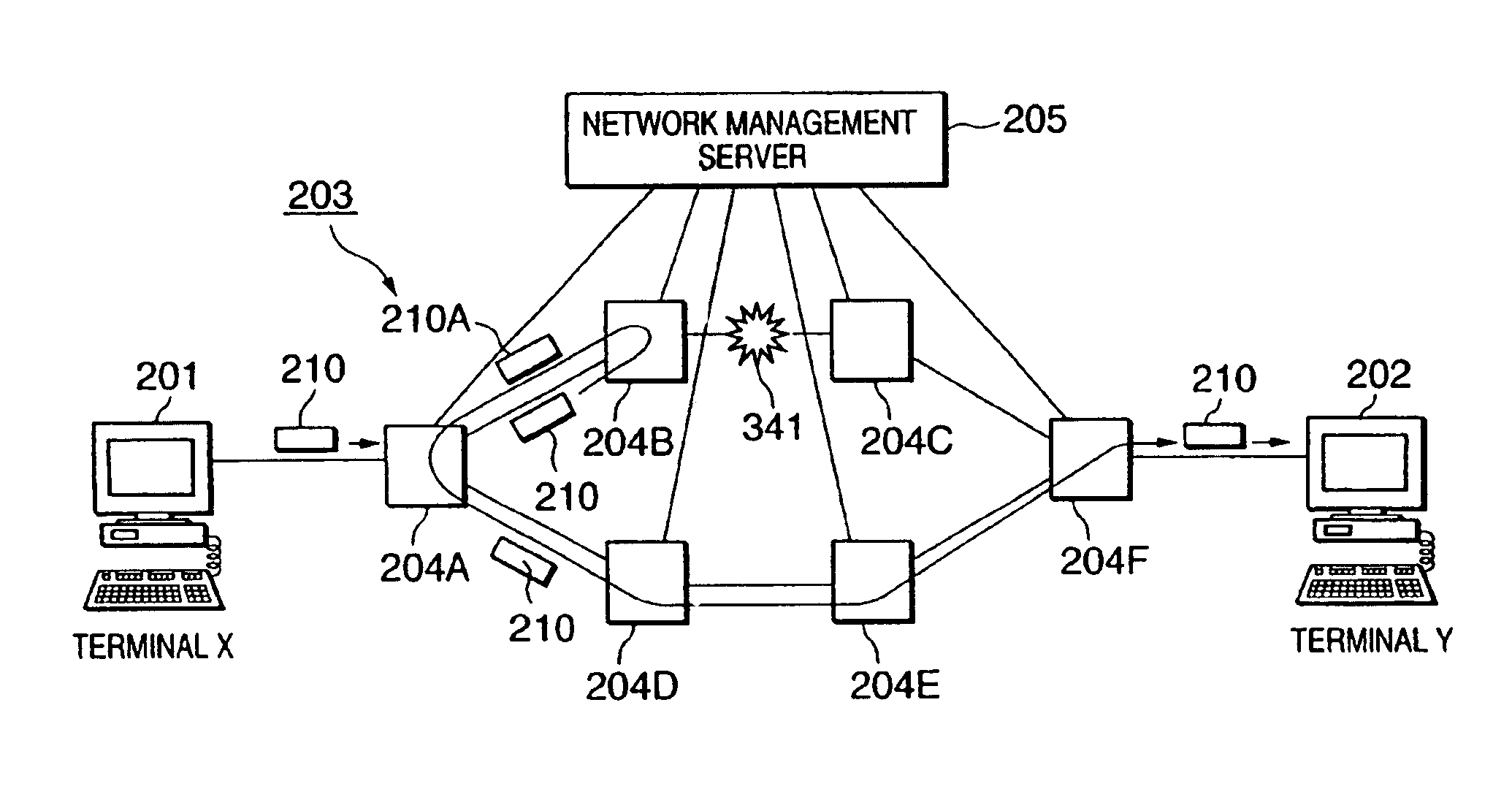
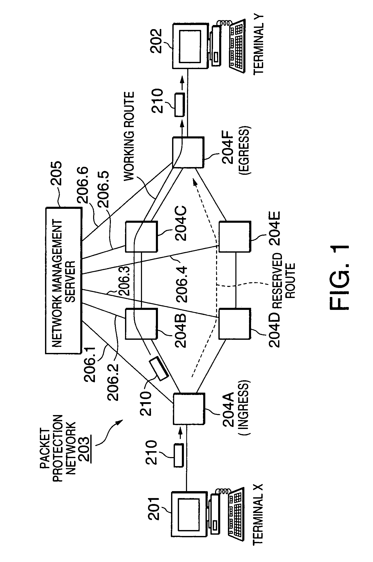
[0026]As shown in FIG. 1, it is assumed for simplicity that a transmission line restoration system according to an embodiment of the present invention is composed of a sending terminal (X) 201, a receiving terminal (Y) 202, a packet protection network 203 composed of routers 204A–204F, and a network management server 205.

[0027]The sending terminal 201 is connected to the router 204A, in this example, which is the ingress to the packet protection network 203. The receiving terminal 202 is connected to the router 204F, in this example, which is the egress from the packet protection network 203. The routers 204A–204F are connected to the network management server 205 through respective ones of control lines 206.1 through 206.6, which may be dedicated lines or be implemented by using an existing network to transfer control data to them.

[0028]It is further assumed that the packet protection network 203 has a working route from the router 204A to the router 204F throug...


PUM


Abstract

A packet protection method allowing rapid restoration in case of fault occurrence without undesired reduction in efficiency on the use of network bandwidth is disclosed. In a packet protection network having a working route and a reserved route set therein, when a failure occurs, a router on the working route sends an incoming packet to be protected back to the ingress router. The ingress router forwards the packet to be protected to the reserved route so that the packet to be protected travels through the reserved route around the failure.

Description

BACKGROUND OF THE INVENTION[0001]1. Field of the Invention[0002]The present invention generally relates to restoration strategies in a packet transfer network composed of a plurality of routers, and in particular to a method and system for restoring data transmission when a fault occurs on a transmission line between routers.[0003]2. Description of the Related Art[0004]There have been proposed restoration strategies for a packet transfer network composed of a plurality of routers, typically, the Internet. An example of a basic restoration method is to switch an initial route to a restored route when a failure has been detected between routers in the initial route. Such a basic restoration method needs to find a new route as an alternative route at its endpoint router by searching its routing table which is being updated according to the routing protocol. Accordingly, it will take much longer until restoration. It is difficult to put it in practical use especially in the field of rea...

Claims


Application Information

Patent Timeline
Patent Type & Authority Patents(United States)
IPC IPC(8): H04L12/26H04L69/40H04L12/42H04L12/437H04L45/24H04L45/247
CPCH04L41/0663H04L45/28H04L45/22H04L45/00
Inventor SHIOZAWA, KENICHI
Owner NEC CORP
Learn More