
Method and device for recording optical data

Inactive Publication Date: 2006-07-11
RICOH KK
View PDF30 Cites 56 Cited by
  • Summary
  • Abstract
  • Description
  • Claims
  • Application Information

AI Technical Summary

Benefits of technology

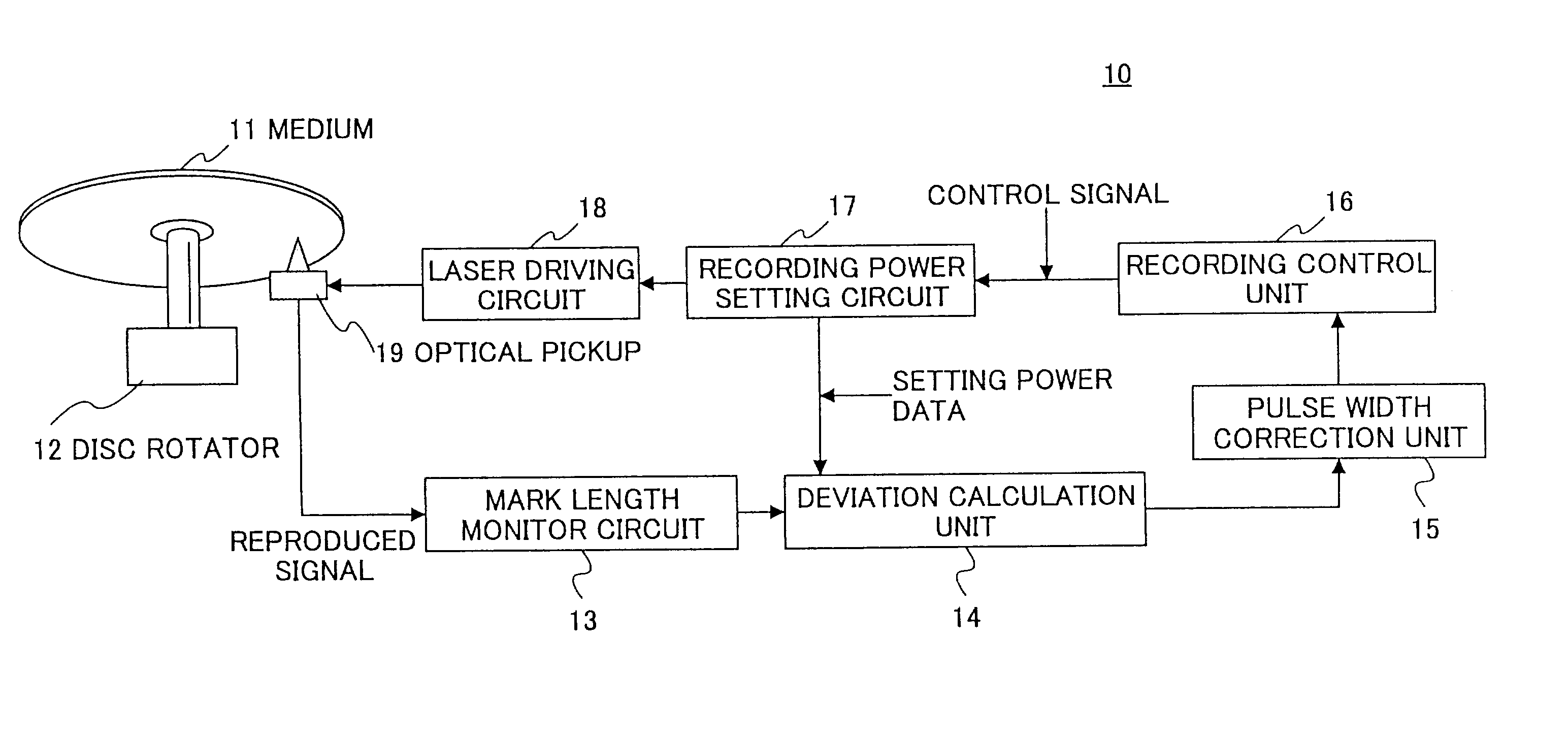
[0018]A more specific object of the present invention is to provide a device and a method for recording optical data able to improve recording power setting during recording by intensity modulation with a small number of pulses.
[0028]According to the above invention, the recording power is set to reduce the deviation between the actual mark lengths and their theoretical lengths to minimum, so setting of the recording power can be optimized even by recording using a small number of pulses.

Problems solved by technology

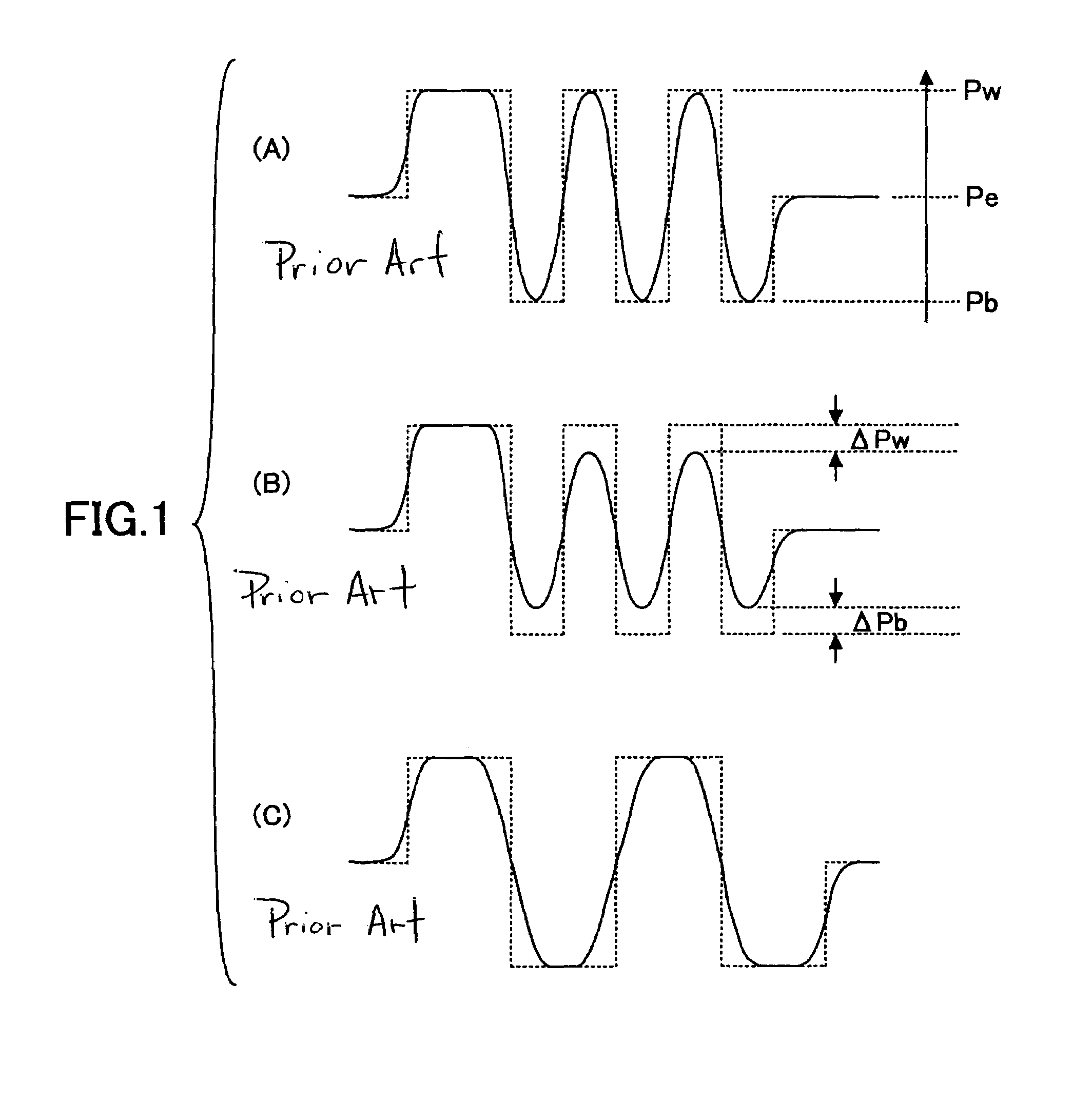
Further, when frequency of the recording channel clock becomes higher, as shown in FIG. 1B, the rising times and the falling times become longer, and sufficiently high recording power (peak value) and sufficiently low bias power (bottom value) cannot be secured.
Recording with pulses of such a pulse shape, the recording material cannot be heated and cooled sufficiently, and it is difficult to secure a slow cooling state.
This difficulty can be overcome if utilizing a light emitting source of short rising and falling times (a laser diode and a driving device thereof), but it is not easy to guarantee a light emitting source working even at frequencies over 100 MHz.
This optimization is difficult, and this method has not been made into practical use.
Using this method, high modulations and good jitter characteristics are obtainable even in optical systems having a low recording power and a low responding performance.

Method used


Image

  • Method and device for recording optical data
  • Method and device for recording optical data
  • Method and device for recording optical data

Examples


example 1

[0157]Discussed below is a method of the related art for setting the recording power Pwo, that is, setting the recording power Pwo by evaluating the modulation.

[0158]FIG. 15 shows dependence of the modulation on the recording power for sample A and sample B. As shown in FIG. 15, the modulation curves of sample A and sample B are different from each other, and their relative relation in the lower power region is reversed in the high power region. Therefore, it is difficult to correctly evaluate the recording power Pwo by the same evaluation means.

example 2

[0159]For CD-RW, a so-called γ parameter is used for evaluation.

[0160]FIG. 16 shows dependence of the γ parameter on the recording power for sample A and sample B. As shown in FIG. 16, the γ parameter shows a larger difference between sample A and sample B than the modulation as shown in FIG. 15. Therefore, drawing the same conclusion, it is difficult to correctly evaluate the recording power Pwo by the same parameter.

[0161]While the present invention has been described with reference to specific embodiments chosen for purpose of illustration, it should be apparent that the invention is not limited to these embodiments, but numerous modifications could be made thereto by those skilled in the art without departing from the basic concept and scope of the invention.

[0162]Summarizing the effect of the invention, according to the present invention as shown above, test recording is performed to correctly evaluate the recording power Pwo to be set. In the test recording, marks having a len...


PUM


Abstract

There is provided a method and a device for recording optical data able to improve recording power setting during recording by means of PWM with a small number of pulses. During the test recording, using a period of a recording channel clock Tw as the minimum unit, marks having different mark lengths of n1·Tw and n2·Tw (n1<n2) are recorded with the same number of m (m<n) light emitting pulses, while successively changing the maximum power Pw of the recording signals. The recorded marks are reproduced and the mark lengths T1 and T2 are measured from the reproduced signals. The recording power can be set by evaluating the deviations D1=T1−n1·Tw and D2=T2−n2·Tw.

Description

BACKGROUND OF THE INVENTION[0001]1. Field of the Invention[0002]The present invention relates to a device and a method for recording optical data to phase-change recording media such as CD-RW, DVD-RAM, DVD-RW, DVD+DW and others.[0003]2. Description of the Related Art[0004]High-speed optical recording media have recently been and continue to be in high demand. Particularly, efforts are being made in increasing the speed of disk-shaped optical recording media, because speed of recording and reproduction of such kind of optical disks can be increased by raising their rotational speed. Among the optical disks, those using optical recording media have simple recording mechanisms because they are capable of recording by only modulating the intensity of the irradiating light, hence it is possible to lower the prices of these media and recording devices. On the other hand, in such kind of devices, since reproduction is achieved also by modulating the intensity of the irradiating light, high...

Claims


Application Information

Patent Timeline
IPC IPC(8): G11B7/00G11B7/0045G11B7/006G11B7/125G11B7/1267G11B20/14H03M5/08
CPCH03M5/08G11B7/1267G11B20/1426G11B7/0062G11B7/00454G11B7/00456
Inventor KATO, MASAKINARUMI, SHINYAYAMADA, KATSUYUKI
Owner RICOH KK
Learn More