Image processing system, image forming system, and recording medium

a technology of image processing and forming system, which is applied in the field of image processing system, image forming system, and recording medium, can solve the problems of interfering between the thin line and the drawing pattern, the above-mentioned and the overall image disappearing of the light thin line, so as to prevent the disappearance of the thin line

Inactive Publication Date: 2006-07-11
FUJIFILM BUSINESS INNOVATION CORP
View PDF9 Cites 2 Cited by
  • Summary
  • Abstract
  • Description
  • Claims
  • Application Information

AI Technical Summary

Benefits of technology

[0028]In the present invention, first the color whose disappearance should be avoided is identified from a plurality of coloring material colors used to reproduce the color of the line segment constituting the input image as the maximum color. Then, the screen parameter is controlled in compliance with the maximum color and the drawing direction of the line segment. At this time, the screen parameter is controlled such that the screen process in the maximum color is carried out at the screen angle that is different from the drawing direction of the line segment. Accordingly, if the screen process is executed by using the controlled screen parameter, the screen process can be carried out at the screen angle, that is different from the drawing direction of the line segment, at least in the maximum color. Therefore, the disappearance of the thin line, the thin-color line, etc. can be prevented.
[0029]Otherwise, the screen parameter is controlled such that the screen process in the maximum color can be carried out at the screen angle, that is different from the screen angle of the line in other drawing directions when the drawing direction of the line segment is a predetermined direction. Accordingly, as for the line segment having the drawing direction that easily disappears at the ordinary screen angle, for example, the screen process can be carried out at the screen angle, that is different from other line segments, at least in the maximum color. Therefore, the disappearance of the thin line, the thin-color line, etc. can be prevented.
[0030]As described above, the disappearance of the thin line is not so generated when the width of the line segment is thick or when the color is deep. Therefore, it is preferable that, if the line segment has a width smaller than a predetermined width or if the line segment has a density thinner than a predetermined density, the change of the screen angle should be executed when the drawing direction of the line segment is close to the screen angle that corresponds to the maximum color. Also, since the yellow is not so striking, other colors may be used preferentially rather than the yellow in identifying the maximum color to prevent the disappearance of other striking colors. In addition, the change of the screen angle can be easily constructed if any one of the screen angles that have mutual mirror image relationships should be selected. Further, if the selected screen angle is selected in the same resolution and line number, the extreme tone change and the degradation of the picture quality such as the density gap at the changed position, etc. can be prevented.

Problems solved by technology

Therefore, when a light thin line is to be drawn, the interference between the thin line and the drawing pattern occurs.
In particular, in the light thin line having the angle that is close to the screen angle, there is the problem that the thin line is not drawn in many infinitesimal areas that successively appear in the extending direction of the thin line and that the light thin line disappears as the overall image.
Thus, it is impossible to prevent the above-mentioned disappearance of the thin line only by switching the resolution.
However, in this case, such approach is not effective to the case where the thin line having the angle close to the screen angle disappears, and thus it is impossible to prevent the disappearance of the thin line.

Method used


Image

  • Image processing system, image forming system, and recording medium
  • Image processing system, image forming system, and recording medium
  • Image processing system, image forming system, and recording medium

Examples


Embodiment Construction

Embodiment of the Invention

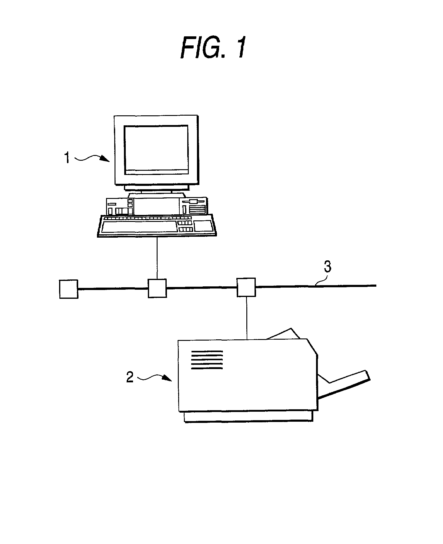
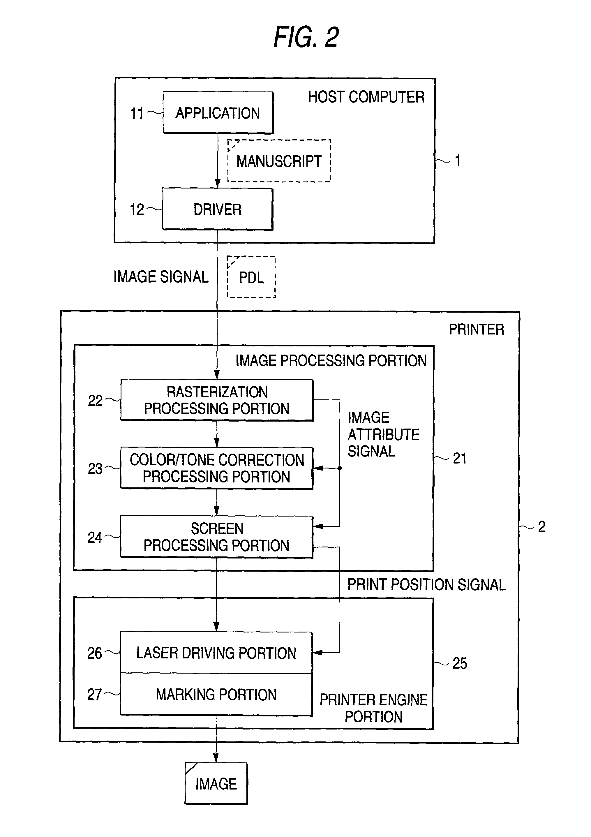
[0041]FIG. 1 is a schematic view showing an example of a configuration of image forming systems containing an embodiment of an image forming system of the present invention. FIG. 2 is a block diagram showing an example of the image forming systems containing the embodiment of the image forming system of the present invention. In FIG. 1 and FIG. 2, 1 is a host computer, 2 is a printer, 3 is a network, 11 is an application, 12 is a driver, 21 is an image processing portion, 22 is a rasterization processing portion, 23 is a color / tone correction processing portion, 24 is a screen processing portion, 25 is a printer engine portion, 26 is a laser driving portion, and 27 is a marking portion. In this example, the image forming system of the present invention shows an example containing the image processing system of the present invention.

[0042]The image forming system shown in FIG. 1 comprises the host computer 1 and the printer 2, and both are connected via the...


PUM


Abstract

A maximum color identifying portion 41 identifies a maximum color from coloring material colors used to reproduce a color of a line segment after color conversion into coloring material colors by a character / line color converting portion 31 is applied to the rasterized image signal. A structure deciding portion 42 outputs a screen parameter flag that controls a screen parameter in compliance with the identified maximum color and a drawing direction of the line segment such that the screen process in the maximum color is executed at a screen angle, that is different from the drawing direction of the line segment, in a character / line screen processing portion 35. The character / line screen processing portion 35 applies the screen process to the image in accordance with the screen parameter flag by using the screen parameter at the screen angle that is different from the drawing direction of the line segment. Accordingly, disappearance of the line segment due to the screen process is avoided.

Description

BACKGROUND OF THE INVENTION[0001]1. Technical Field[0002]The present invention relates to an image processing system and an image forming system for applying a screen process to an input image, and a recording medium for storing a program that causes a computer to execute such process.[0003]2. Related Art[0004]In the color image forming system, the color reproduction in full color can be achieved by using a plurality of coloring materials. The color image is formed by superposing the corresponding color image every coloring material. In superposing respective color images, slight displacement is caused due to the precision. The displacement in the superposition causes the generation of the moire, etc. on the image.[0005]In order to prevent the generation of the moire, etc. due to the displacement in the superposition of respective color images, normally the rotation screen in which the screen angle to the image in the screen process is changed every coloring material color is employ...

Claims


Application Information

Patent Timeline
Patent Type & Authority Patents(United States)
IPC IPC(8): H04N1/40B41J5/30B41J2/52B41J2/525G06F3/12G06K15/02G06T5/00H04N1/52H04N1/60
CPCG06K15/02G06K2215/0094
Inventor KITAGAWARA, ATSUSHI
Owner FUJIFILM BUSINESS INNOVATION CORP
Why Eureka
Try Eureka