Fuel injection valve with a filter bush

a technology of fuel injection valve and filter bush, which is applied in the direction of fuel injection apparatus, fuel feed system, engine components, etc., can solve the problems of large processing time spent attaching the filter, fuel injector malfunction, and fuel injector malfunction

Inactive Publication Date: 2006-07-04
ROBERT BOSCH GMBH
View PDF10 Cites 11 Cited by
  • Summary
  • Abstract
  • Description
  • Claims
  • Application Information

AI Technical Summary

Benefits of technology

[0006]The fuel injector of the present invention has the advantage over the background art that the sleeve for adjusting the dynamic flow rate is formed in one piece with the filter element, and therefore, on one hand, the position of the sleeve may easily be adjusted using the protruding filter element, and, on the other hand, quick and inexpensive manufacturing and assembly are rendered possible.
[0007]In this context, the combined filter sleeve is inexpensively manufactured by deep-drawing, so that a plastic frame having a filter grating attached to it may be dispensed with.
[0009]In particular, it is also advantageous that the flow rate may be adjusted with the filter already inserted, since contamination of the valve interior may be prevented by the adjusting tools.
[0010]Furthermore, it is advantageous that the filter sleeve may also be removed again, if necessary.

Problems solved by technology

This manner of fastening involves the risk of dust and cuttings forming, which can lead to the malfunction of the fuel injector.
A particular disadvantage of the fuel injectors known from the above-mentioned, printed publications is the large amount of processing time spent in attaching the filter to either the adjusting sleeve or the fuel intake nipple.
In addition, the filter and adjusting sleeve are made of different materials, whereby cuttings and dust are formed at the contact surfaces, predominantly on the plastic of the filter, which can lead to the malfunction of the fuel injector caused by the deposition of the particles.

Method used


Image

  • Fuel injection valve with a filter bush
  • Fuel injection valve with a filter bush
  • Fuel injection valve with a filter bush

Examples


Embodiment Construction

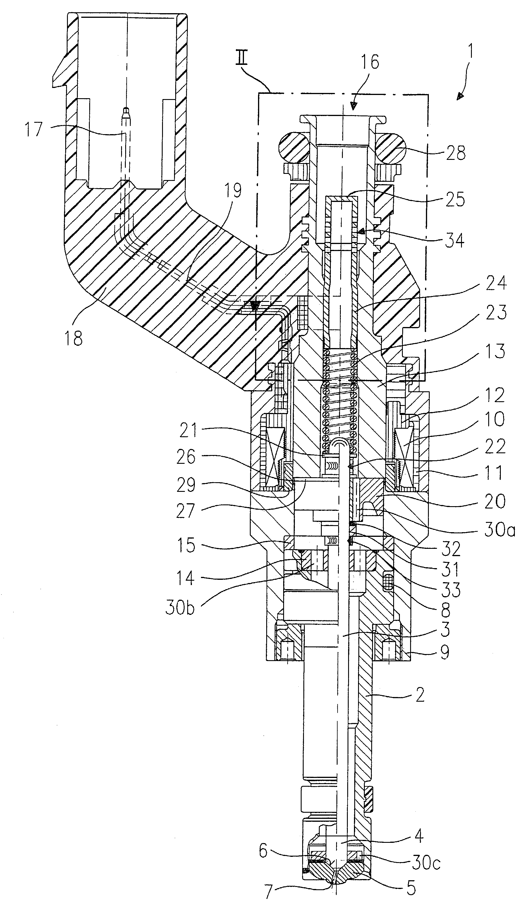
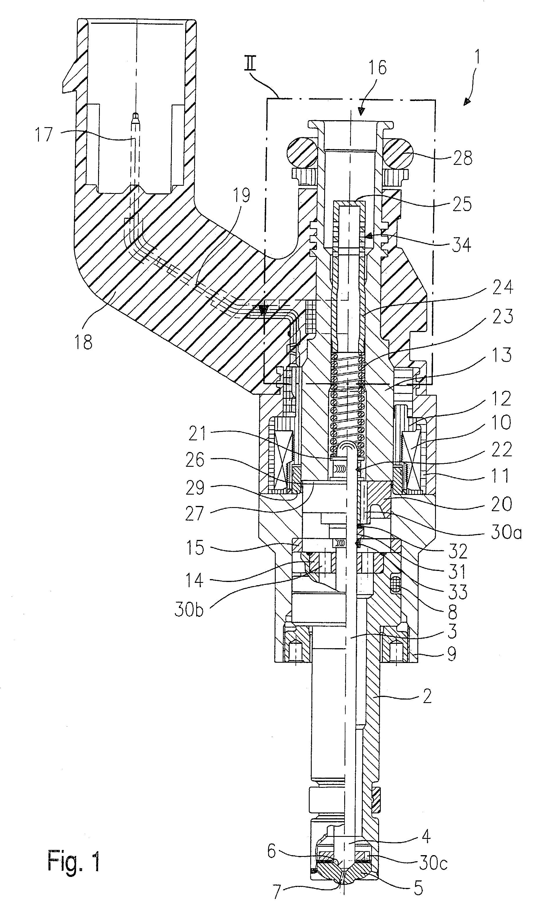
[0013]A fuel injector 1 is designed, for example, in the form of an injection valve for fuel-injection systems of mixture-compressing, spark ignition engines. The fuel injector 1 represented is suitable for the direct injection of fuel into a combustion chamber, not shown, of an internal combustion engine. However, the present invention is also similarly suitable in the case of fuel injectors 1 for the injection of fuel into an intake manifold of the engine.

[0014]Fuel injector 1 includes a nozzle body 2, in which a valve needle 3 is guided. Valve needle 3 is mechanically linked to a valve-closure member 4, which interacts with a valve-seat surface 6 positioned on a valve-seat member 5, to form a sealing seat. The fuel injector 1 in the exemplary embodiment is an inwardly opening fuel injector 1, which has a spray orifice 7. Nozzle body 2 is sealed from an outer pole 9 of a solenoid coil 10 by a seal 8. Solenoid coil 10 is encapsulated in a coil housing 11 and wound onto a coil brace...


PUM


Abstract

A fuel injector for fuel-injection systems of internal combustion engines has a solenoid coil; a valve needle that is mechanically linked to the solenoid coil and acted upon by a restoring spring in a closing direction, in order to actuate a valve-closure member which, together with a valve-seat face, forms a sealing seat; and a sleeve, which prestresses the restoring spring. The sleeve is integrally formed with a filter element to form a one-part, deep-drawn filter sleeve, which has through-flow openings for filtering the fuel flowing through the fuel injector.

Description

FIELD OF THE INVENTION[0001]The present invention relates to a fuel injector.BACKGROUND INFORMATION[0002]In the case of fuel injectors already known, fuel filters are press-fit into a fuel intake nipple and, thus, secured in place in it. This manner of fastening involves the risk of dust and cuttings forming, which can lead to the malfunction of the fuel injector. In addition, retaining collars for upper sealing rings are constructed as individual component parts.[0003]A fuel injector, in which a fuel filter is manufactured in one piece with a retaining collar, is already known from German Published Patent Application No. 43 25 842. The retaining collar radially extends beyond the fuel intake nipple and has a lip outside the fuel intake nipple. The circumferential lip of the retaining collar forms, together with a groove on the outer circumference of the fuel intake nipple, a snap-in connection, by which the fuel filter is fastened in a defined manner. There is only a clearance fit ...

Claims


Application Information

Patent Timeline
Patent Type & Authority Patents(United States)
IPC IPC(8): B05B1/30F02M39/00F02M61/10F02M51/06F02M61/16F02M63/00
CPCF02M51/0671F02M61/168F02M61/165F02M2200/505
Inventor MAIER, DIETER
Owner ROBERT BOSCH GMBH
Why Eureka
Try Eureka