Eureka AIR delivers breakthrough ideas for toughest innovation challenges, trusted by R&D personnel around the world.

Alarm control system and method

a technology of alarm control and communication network, which is applied in the field of alarm control system for optical wavelengthdivision multiplexing (wdm) communications network, can solve the problems of increasing the network manager cannot immediately localize the failure of the optical communication system, etc., and achieves the effect of reducing the amount of traffic in the management network and facilitating the localization of failures

Inactive Publication Date: 2006-06-27
NEC CORP
View PDF6 Cites 34 Cited by
  • Summary
  • Abstract
  • Description
  • Claims
  • Application Information

AI Technical Summary

Benefits of technology

[0008]An object of the present invention is to provide alarm control system and method allowing easy localization of a failure in an optical communications network.
[0009]Another object of the present invention is to provide alarm control system and method which permits a single alarm signal to be issued for a single failure.
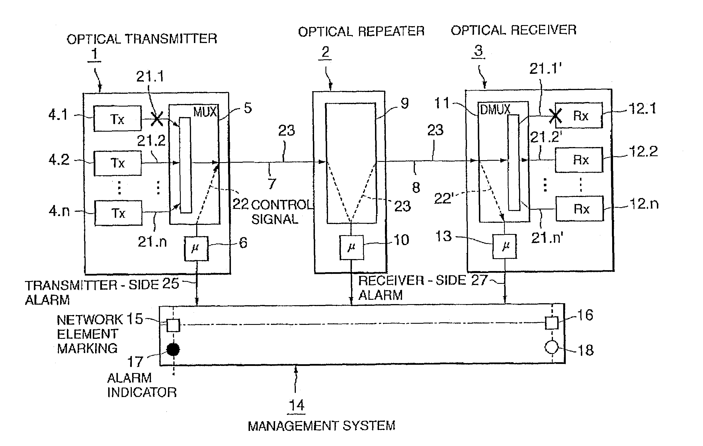
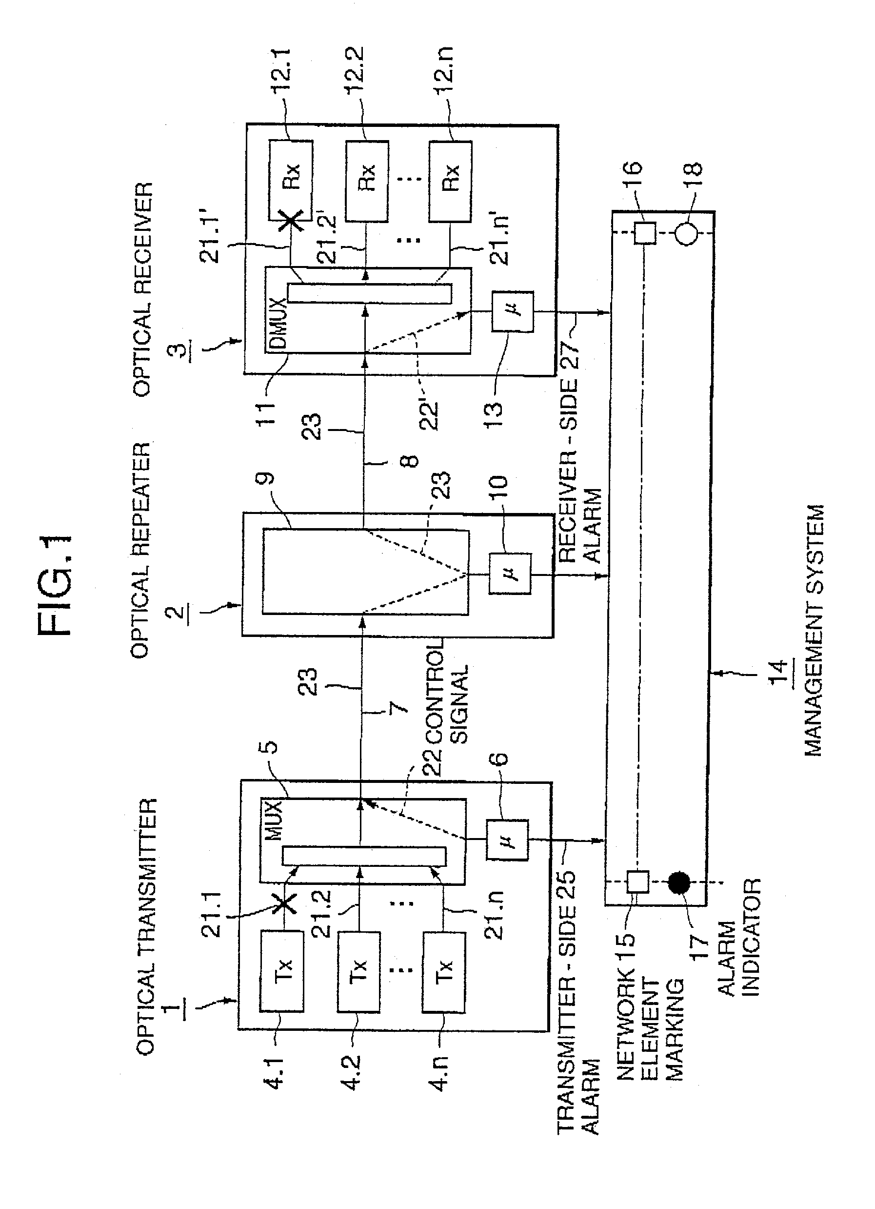
[0018]As described above, when a failure such that an optical signal is not normally inputted occurs only at the transmitting terminal, the receiving terminal does not transmit the receiver-side alarm signal to the management system. Accordingly, the management system receives only the transmitter-side alarm signal from the transmitting terminal. In other words, a single alarm signal is permitted to be issued for a single failure. Since the management system notifies a network manager of occurrence of a failure at the transmitting terminal, easy localization of the failure can be achieved.
[0019]Further, in this case, the receiving terminal does not transmit the receiver-side alarm signal to the management system and therefore the amount of traffic in the management network can be reduced.

Problems solved by technology

The network manager cannot immediately localize the failure on the optical communications system.
Further, two alarm signals are sent to the management system for a single failure, the amount of traffic in the management network is increased.

Method used


Image

  • Alarm control system and method
  • Alarm control system and method
  • Alarm control system and method

Examples


Embodiment Construction

Optical WDM Communications System

[0025]As shown in FIG. 1, it is assumed for simplicity that an optical transmitter 1 transmits an optical WDM signal to an optical receiver 3 through an optical repeater 2. The optical transmitter 1 and the optical repeater 2 are connected through an optical transmission line 7. The optical repeater 2 and the optical receiver 3 are connected through an optical transmission line 8. The optical transmitter 1, the optical repeater 2 and the optical receiver 3 are also connected to a management system 14 through a management network (not shown).

[0026]The optical transmitter 1 includes n signal transmitters 4.1–4.n (n is an integer greater than 1), which each output optical transmission signals 21.1–21.n to a wavelength multiplexer 5. The optical transmission signals 21.1–21.n have different wavelengths on respective ones of non-overlapping wavelength bands, each of which is assigned to a different WDM channel.

[0027]The optical transmitter 1 is further pr...


PUM


Abstract

An alarm control method allowing easy localization of a failure in an optical communications network is disclosed. An optical signal from a signal transmitter is monitored to produce an alarm information signal indicating whether the optical signal is normally inputted. The optical signal and an optical control signal including the alarm information signal is multiplexed and transmitted to an optical receiver through an optical transmission line. When receiving the optical control signal and the optical signal from the optical transmitter, the optical receiver determines whether the optical signal is normally received. When not normally received, transmission of a receiver-side alarm signal to a management system is controlled depending on whether the alarm information signal indicates that the optical signal has been normally inputted at the optical transmitter.

Description

BACKGROUND OF THE INVENTION[0001]1. Field of the Invention[0002]The present invention generally relates to an optical communications system and in particular to an alarm control method and system for an optical Wavelength-Division Multiplexing (WDM) communications network.[0003]2. Description of the Related Art[0004]For optical high-capacity communication networks using optical transmission lines (typically, optical fibers), Wavelength-Division Multiplexing (WDM) is the current favorite multiplexing technology since multiple WDM channels from different end users can be multiplexed on the same optical fiber. Accordingly, there have been widely used optical WDM communications systems, some of which have a management system for managing network elements including terminals and repeaters thereof.[0005]It is assumed for simplicity that a source terminal transmits an optical WDM signal to a destination terminal through a repeater, which are connected to a management system through a manag...

Claims


Application Information

Patent Timeline
IPC IPC(8): H04B10/08H04B10/07H04B10/077H04B10/291H04B17/00H04J14/00H04J14/02H04L69/40
CPCH04B10/07H04B10/0771H04B2210/072H04B2210/071
Inventor TOKUNAGA, KOICHI
Owner NEC CORP
Why Eureka
Eureka Blog
Learn More