
Receiver for a spread spectrum system

a technology of spread spectrum and receiver, applied in the field of receivers, can solve the problems of common measurement errors in the creation of range measurements, and achieve the effects of improving the reception of transmitted signals and synchronisation thereof, reducing the number of errors, and improving the sensitivity of transmission signals

Inactive Publication Date: 2006-06-27
RPX CORP
View PDF5 Cites 6 Cited by
  • Summary
  • Abstract
  • Description
  • Claims
  • Application Information

AI Technical Summary

Benefits of technology

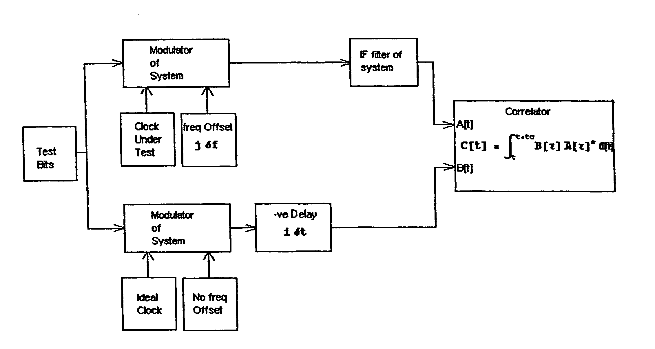
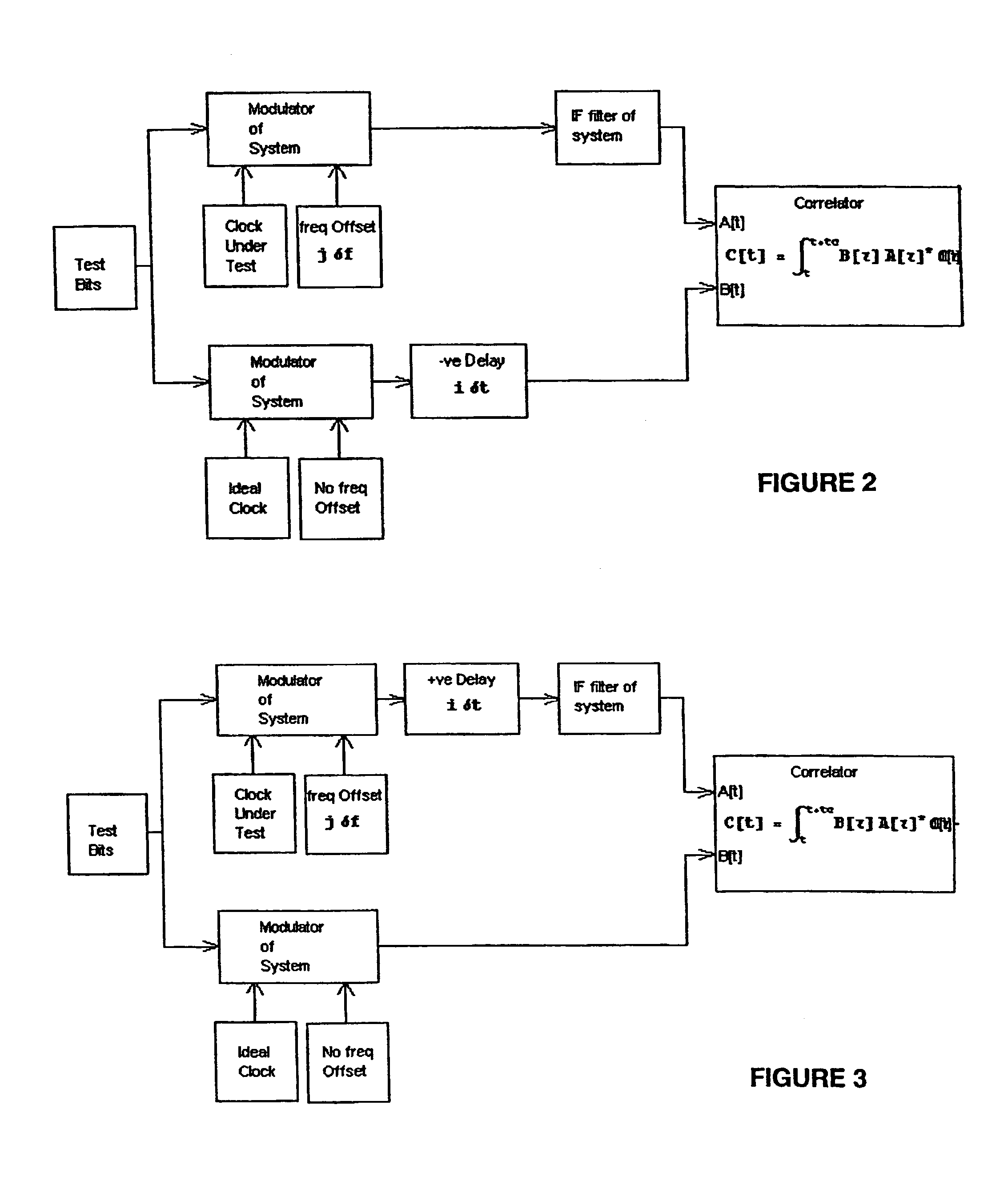
The present invention provides a method for operation of a receiver of a spread spectrum system that can accurately synchronize and demodulate weak signals. The method uses a predefined correlation surface and an expected signal to correlate the received signal with. The correlation measure is then compared with a computational expression to determine the time offset and frequency offset. This algorithm allows for the simultaneous identification of the actual offsets and time, making the process more efficient. The invention is particularly useful in tracking and demodulation of weak signals, making it feasible to obtain synchronization without prior knowledge of the transmitted bit sequence.

Problems solved by technology

It should be noted, however, that range measurement inherently contain errors common to measurements created by the unsynchronised operation of the satellite and the user clocks.

Method used


Image

  • Receiver for a spread spectrum system
  • Receiver for a spread spectrum system
  • Receiver for a spread spectrum system

Examples


example

[0110]The following example of a preferred implementation of the present invention in an example run in the computer program Mathematica 4.

[0111]One method that can be used for finding the values is given in the following example for

τ0

and

μ0

[0112]Any assumptions involved in the demonstration in that there exists exactly one path such that

−Δt[m]+ΔtRe[n]=0.4Tc

[0113]For all other paths it is assumed:

Abs[−Δt[m]+ΔtRe[n]]>3Tc

f−f0−Δf[m]=0.35 Hz

[0114]Let the strength

α[m]=0.8

[0115]Assume B[k]=1;

[0116]In the sequel, all the time units are in Tc, chip periods and all the frequencies are in Hz.

[0117]This assumption is consistent with the system tracking one path. Under these assumptions the following is arrived at:

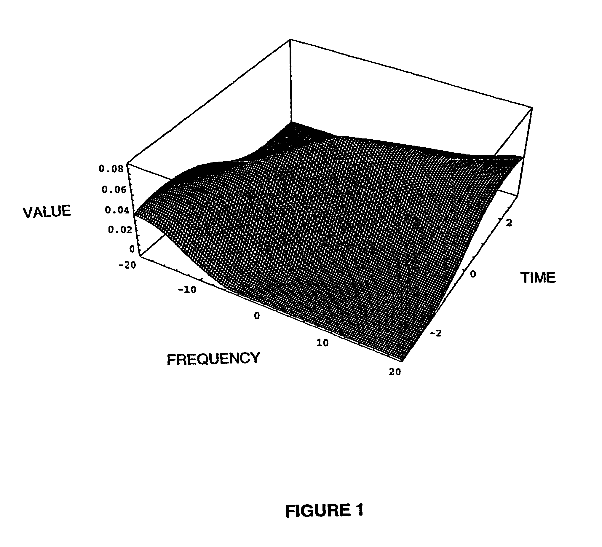
Γ[n][μ, τ]=0.8 CorrelatingSurface [μ+0.35, τ+0.4]

[0118]For GPS the correlation surface function is calculated to be:

[0119]CorrelationSurface⁡[{μ_,τ_}]:=⁢1.0282397173771807⁢‵-⁢0.6561546163982793⁢‵⁢μ+⁢0.16121834444658398⁢‵⁢μ2-⁢0.041119148280990614⁢‵⁢τ+⁢0.531238073030845⁢‵⁢μτ-⁢0.567170671...


PUM


Abstract

A method for operation of a receiver of a spread spectrum system. The method includes generating in the receiver an expected signal, the expected signal being a function of time and frequency correlating the received time and frequency of the received signal with time and frequency shifted parameters of the expected signal deriving a computational expression indicative of the value of the correlation at a point displaced in time by the time offset plus the time shift and displaced in frequency by the frequency offset plus the frequency shift, and comparing the correlation measure with the computational expression to determine the time offset and the frequency offset.

Description

BACKGROUND OF THE INVENTION[0001]The present invention is applicable in spread spectrum telecommunication systems and more specifically relates to receivers for use in such systems.[0002]In telecommunications, two common examples of spread spectrum systems are CDMA and WCDMA. Other examples include the Global Positioning System (GPS). Global positioning system (GPS) is one example of a space based satellite navigation system that has the ability to pinpoint any location on earth with a high degree of accuracy, providing information on position, velocity and time (PVT) of a receiver. Other examples of spaced based satellite navigation system are TIMATION, transit, and GLONASS.[0003]GPS is typically divided into three segments:[0004]a space segment which essentially comprises the satellites and the signals they emit,[0005]a control segment which monitors and maintains the satellite constellation,[0006]a user segment which comprises GPS receivers, equipment, data collection and data pr...

Claims


Application Information

Patent Timeline
Patent Type & Authority Patents(United States)
IPC IPC(8): H04B1/69H04B1/707
CPCH04B1/7075H04B1/707
Inventor LOBODOSSAJI, TAI
Owner RPX CORP
Learn More