Method and apparatus for the remote control of an operating table

Active Publication Date: 2006-06-27
TRUMPF MEDIZIA SYST GMBH CO KG
View PDF8 Cites 91 Cited by
  • Summary
  • Abstract
  • Description
  • Claims
  • Application Information

AI Technical Summary

Benefits of technology

[0009]This object is achieved according to the invention in the case of a method of the type stated at the beginning by an infrared control signal first being emitted to the operating table by the operator control unit before the transmission of command signals and the reception of the control signal from the operator control unit being confirmed by radio signal. The transmission of the infrared control signal from the operator control unit to the operating table ensures that there is a visual link between the operator control unit and the operating table to be operated. As a result, a unique association between the items of equipment is ensured in a constructionally simple way. Only the operating table which is located in the room in which the operator control unit—for example in the form of a wall-mounted console—is positioned can be operated. Inadvertent adjustment of an operating table which is located in a neighboring room is avoided in this way. The transmission of the confirmation signal takes place in this case in the form of a radio signal, with the advantages of a high data transmission rate and a stable connection.
[0010]It is advantageous if the drive device can only be activated after the operator control unit has received the radio signal from the operating table confirming reception. Consequently, the activation of the drive device can only take place when the operating table emits a confirmation signal and this has been received by the operator control unit.
[0011]It is of particular advantage if the command signals are transmitted between the operator control unit and the operating table in the form of radio signals. In this case, a bidirectional radio link can be used, so that high data transmission rates can be achieved in both directions and a stable connection can be maintained.
[0013]In the case of an advantageous embodiment of the method according to the invention, it is provided that infrared control signals are repeatedly emitted by the operator control unit at predetermined intervals—preferably periodically—and in each case the reception of a confirmation signal from the operating table is monitored. This permits virtually continuous monitoring of the association between the operator control unit and the operating table. The repeated emission of infrared control signals also has the advantage that an operating table which is brought into the room in which the operator control unit is located is automatically detected by the operator control unit, so that an association between the operator control unit and this operating table is established.
[0017]It is of advantage if the drive device can only be activated when the operator control unit has received the confirmation signal.
[0020]It is advantageous if infrared control signals can be repeatedly emitted by the operator control unit at predetermined intervals—preferably periodically—and in each case the reception of a confirmation signal can be monitored. For this purpose, the operator control unit may comprise a monitoring unit, which ensures that command signals can only be emitted if a confirmation signal from the operating table has previously been received.

Problems solved by technology

However, infrared transmission permits only very limited data transmission rates and optically opaque obstacles prevent data transmission.
If the communication between the operator control unit and the operating table takes place by radio, there is however the associated difficulty that the connection of the items of equipment is maintained even when the operating table is moved out of the room in which it was previously operated by means of the operator control unit.
There is consequently the risk that the operator control unit in the form of a separate unit may inadvertently activate the wrong operating table, for example a table which is not positioned in the operating room but in a neighboring room.

Method used


Image

  • Method and apparatus for the remote control of an operating table
  • Method and apparatus for the remote control of an operating table

Examples


Embodiment Construction

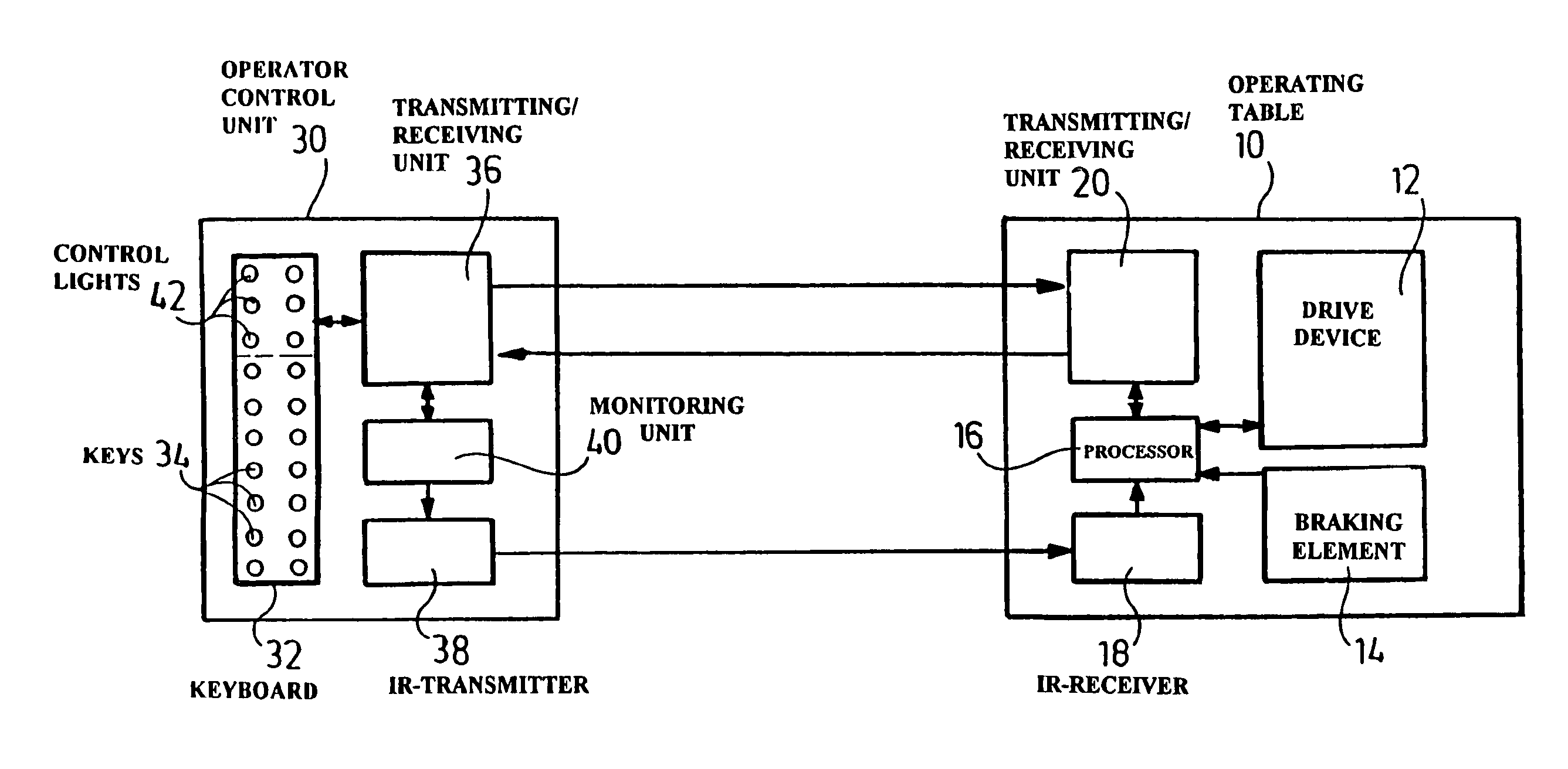
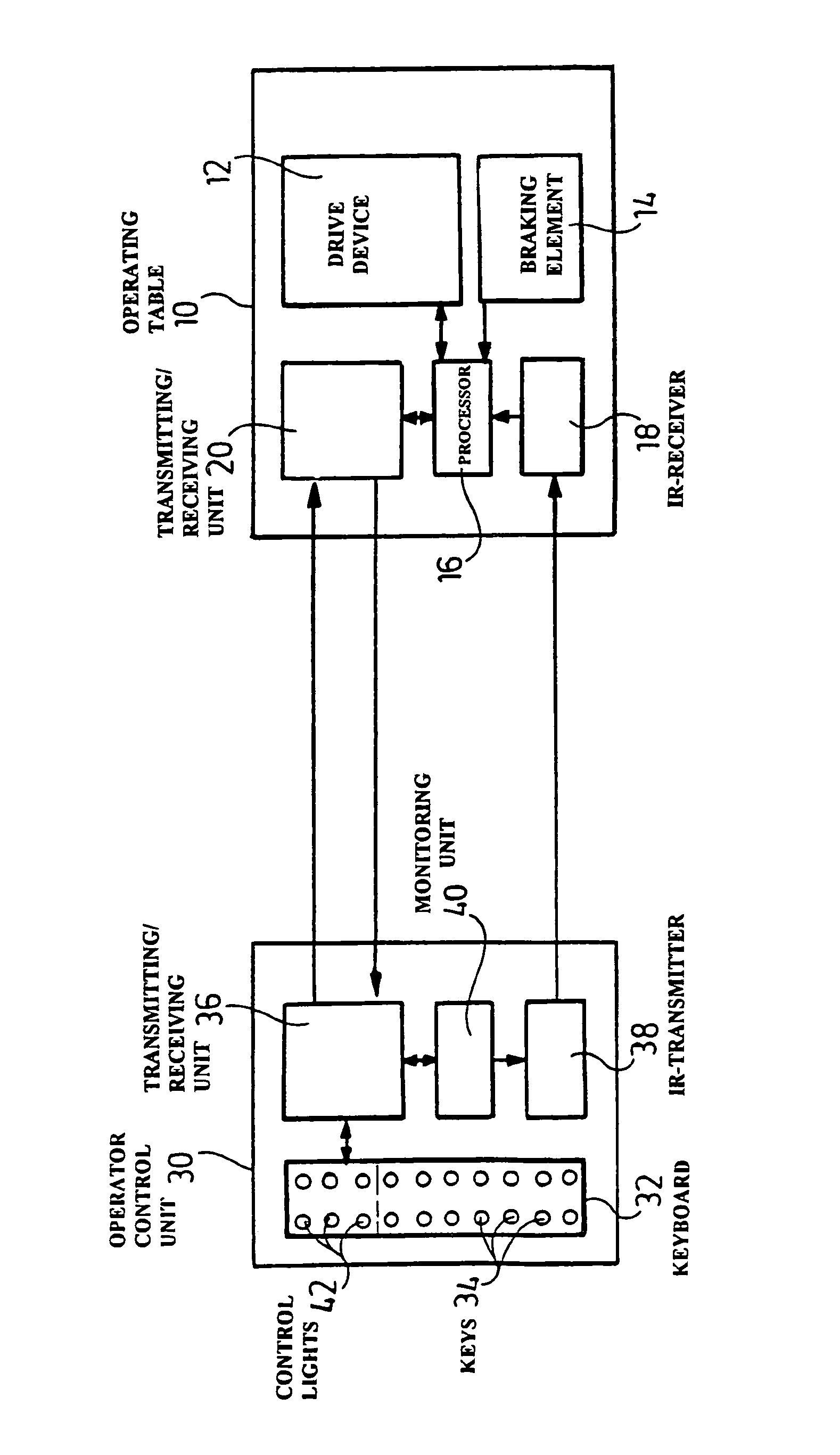
[0025]The operating table is designated by the reference numeral 10 and comprises, in a way which is known and therefore not represented in the drawing, a height-adjustable supporting column, on which a table top with a plurality of pivotably mounted table top elements is supported. The table top may comprise, for example, a base element, which can be releasably connected to the supporting column, and also a back element and a foot element, which are respectively hinge-mounted on the base element and can be pivoted in relation to the latter about horizontal axes. In addition, the base element can be displaced in the longitudinal direction of the operating table in relation to the supporting column. Operating tables of this type are known per se and described for example in DE 197 51 320 A1.

[0026]The operating table top 10 comprises a drive device 12 in the form of an electric drive known per se, which may, for example, be integrated into the operating table top or into the supportin...


PUM


Abstract

Remote control of an operating table which can be motor-adjusted by means of a drive device is provided for. Command signals for controlling the drive device are wirelessly transmitted to the operating table from an operator control unit. A unique association between the operator control unit and an operating table is ensured before command signals are sent by emitting an infrared control signal to the operating table by the operator control unit and then confirming the reception of the control signal from the operator control unit by radio signal from the operating table.

Description

[0001]The present disclosure relates to the subject matter disclosed in European application No. 01127644.1 of Nov. 20, 2001, which is incorporated herein by reference in its entirety and for all purposes.BACKGROUND OF THE INVENTION[0002]The invention relates to a method for the remote control of an operating table which can be motor-adjusted by means of a drive device, command signals for controlling the drive device being wirelessly transmitted to the operating table from an operator control unit.[0003]The invention also relates to an apparatus for carrying out the method.[0004]Operating tables are increasingly being made in a multi-part form and often comprise a height-adjustable supporting column and an operating table top with at least one pivotably mounted table top element. The operating table usually also has an electromotive drive device for adjusting the at least one table top element and the supporting column. The control of the drive device takes place by the input of ap...

Claims


Application Information

Patent Timeline
IPC IPC(8): G05B23/02A61G13/02
CPCA61G13/02G05B2219/25192G05B2219/25187A61G2203/12
Inventor DOERING, ULRICHSTREITBERGER, CHRISTIANGEORGI, FALK
Owner TRUMPF MEDIZIA SYST GMBH CO KG
Why Eureka
Try Eureka