
Miniaturized multi-layer balun

a multi-layer balun and miniaturization technology, applied in the direction of multiple-port network, electrical equipment, waveguides, etc., can solve the problems of not being able to further reduce in size, reaching the limit of miniaturization, and not being able to maintain the identical magnitude of 180-degree phase difference between the two signals, etc., to achieve the effect of reducing the size of the balun, reducing the cost, and simple manufacturing process

Active Publication Date: 2006-06-27
IND TECH RES INST
View PDF6 Cites 30 Cited by
  • Summary
  • Abstract
  • Description
  • Claims
  • Application Information

AI Technical Summary

Benefits of technology

The design achieves a compact form factor, improved manufacturing yield, and enhanced stability, maintaining effective impedance matching and phase difference across the operating frequency range, while reducing the number of layers required, thus lowering production costs and increasing precision.

Problems solved by technology

However, it is not easy to maintain the 180-degree phase difference and the identical magnitude between the two signals.
When a coil-type balun is used in higher than the UHF band, it usually has a drawback of having considerable loss.
In addition, it has reached the limit of miniaturization and can not be further reduced in size.
However, its size often poses a problem when it is used in the radio frequency range between 200 MHz and several GHz.
Because a 180-degree hybrid balun comprises a few sections of quarter wave transmission lines, it is difficult to reduce the size.
Even if it is manufactured in a meandered way, a significant area is still required.
Nevertheless, the size is still too large.
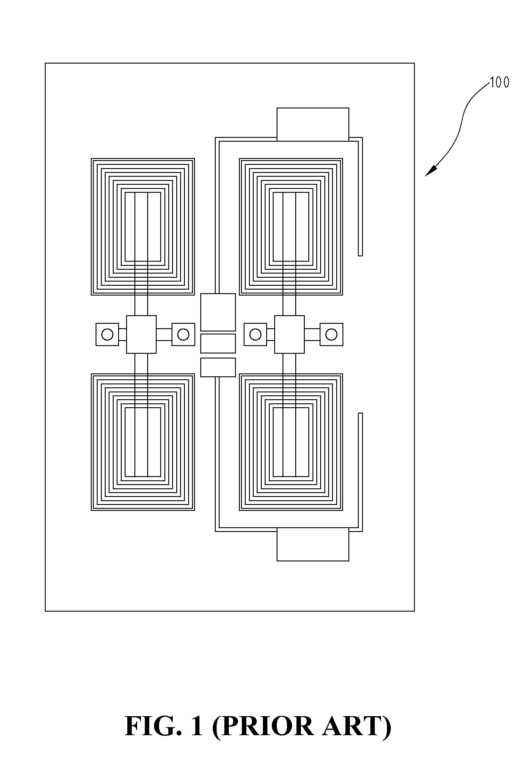
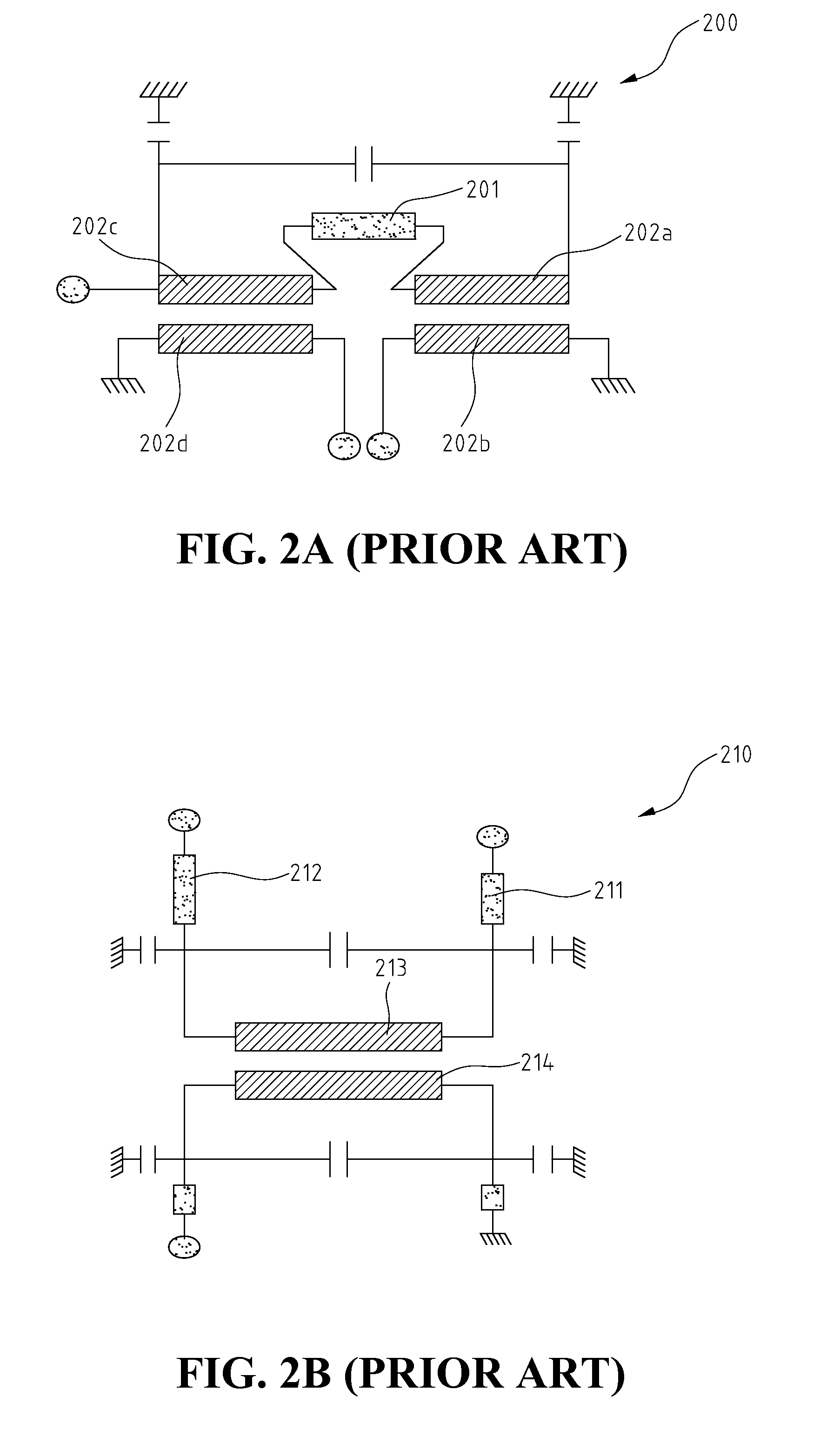
However, the disadvantage of the design is that it requires a plurality of passive elements, and when a sensitive passive element has a slight deviation from its original design due to the manufacture process, the entire design will exhibit a different characteristics.
In addition, the planar design also requires a larger space.
The disadvantage of the embodiment in FIG. 2B is that it uses the scheme of half wavelength to obtain the ground equivalent to quarter wavelength to the coupled line center.
In addition, the balun uses 6–8 metal layers; therefore, the effectiveness of the balun is very sensitive to the alignment precision of the multi-layer structure during the manufacturing process.
The disadvantage of the balun 220, as in the other conventional arts is that it uses the half wavelength scheme to obtain the ground equivalent to quarter wavelength to the coupled line center.

Method used


Image

  • Miniaturized multi-layer balun
  • Miniaturized multi-layer balun
  • Miniaturized multi-layer balun

Examples


Embodiment Construction

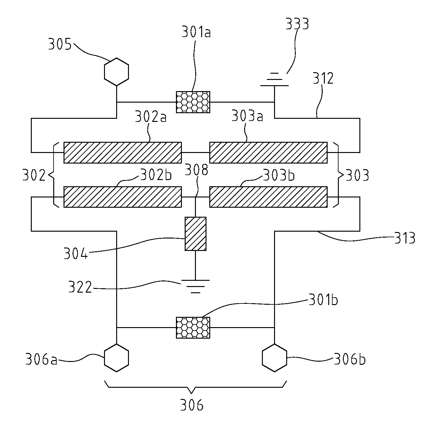
[0020]FIG. 3A shows the equivalent circuit 300 of a preferred embodiment of miniaturized multi-layer balun according to the present invention. The equivalent circuit 300 comprises a pair of capacitive elements 301a and 301b that are on the sides connecting to the unbalanced and balanced I / O ports respectively, one section of broadside coupled lines 302, another section of broadside coupled lines 303, a pair of transmission lines 312 and 313, and a ground connection 304 that is on the side connecting to two balanced I / O ports 306a and 306b.

[0021]As can be seen in FIG. 3A, each capacitive element has two ends. One end of capacitive element 301a is connected to ground 333, and the other end is connected to the unbalanced I / O port 305. Both ends of capacitive element 301b are connected to the two balanced I / O ports 306a, 306b respectively. The section of broadside coupled lines 302 further includes a first coupled line 302a and a second coupled line 302b. The section of broadside coupl...


PUM


Abstract

A miniaturized multi-layer balun includes a pair of capacitive elements, at least one section of broadside coupled lines connected in series to an unbalanced and two balanced ports through a pair of transmission lines. Each section has first and second coupled lines. A ground connection is located between two central second coupled lines, and connected to a ground. By means of a multi-layer structure and the addition of a ground connection, the balun of the invention can be fabricated with five conductor layers. This not only greatly decreases the size of the balun device, but also enhances the stability of the device. From the measured return loss and differences in magnitude and phase to the frequency response, it shows that the balun of the invention has good impedance match.

Description

FIELD OF THE INVENTION[0001]The present invention generally relates to a balance-to-unbalance transformer (balun) used in a wireless communication, and more specifically to a miniaturized multi-layer balun.BACKGROUND OF THE INVENTION[0002]A balance-to-unbalance transformer is one of the most commonly used passive elements in wireless communication systems. A balun is a device for converting signals between an unbalanced circuit structure and a balanced circuit structure. The signal of a balanced circuit structure comprises two signal components, called balanced differential signals, which are with same magnitude but 180-degree phase difference. The transmission of differential signals can be used to reduce the common mode noise interference. Therefore, a balun is usually designed in a part of a radio frequency (RF) transceiver, power amplifier (PA), antenna and mixer circuit.[0003]There are several types of baluns, including lumped-type (lattice type), coil-type and distributed-type...

Claims


Application Information

Patent Timeline
Patent Type & Authority Patents(United States)
IPC IPC(8): H01P5/10H03H7/42
CPCH01P5/10
Inventor WENG, CHING-LIANGCHEN, CHANG-SHENGLAI, YING-JIUNNJOW, UEI-MINGSHYU, CHIN-SUN
Owner IND TECH RES INST
Learn More