Chassis structure for vehicles
a chassis and chassis technology, applied in the direction of roofs, transportation and packaging, vehicle arrangements, etc., can solve the problem of insufficient utilization of crushable zones of size members, and achieve the effect of effective absorption of impa
- Summary
- Abstract
- Description
- Claims
- Application Information
AI Technical Summary
Benefits of technology
Problems solved by technology
Method used
Image
Examples
embodiment 1
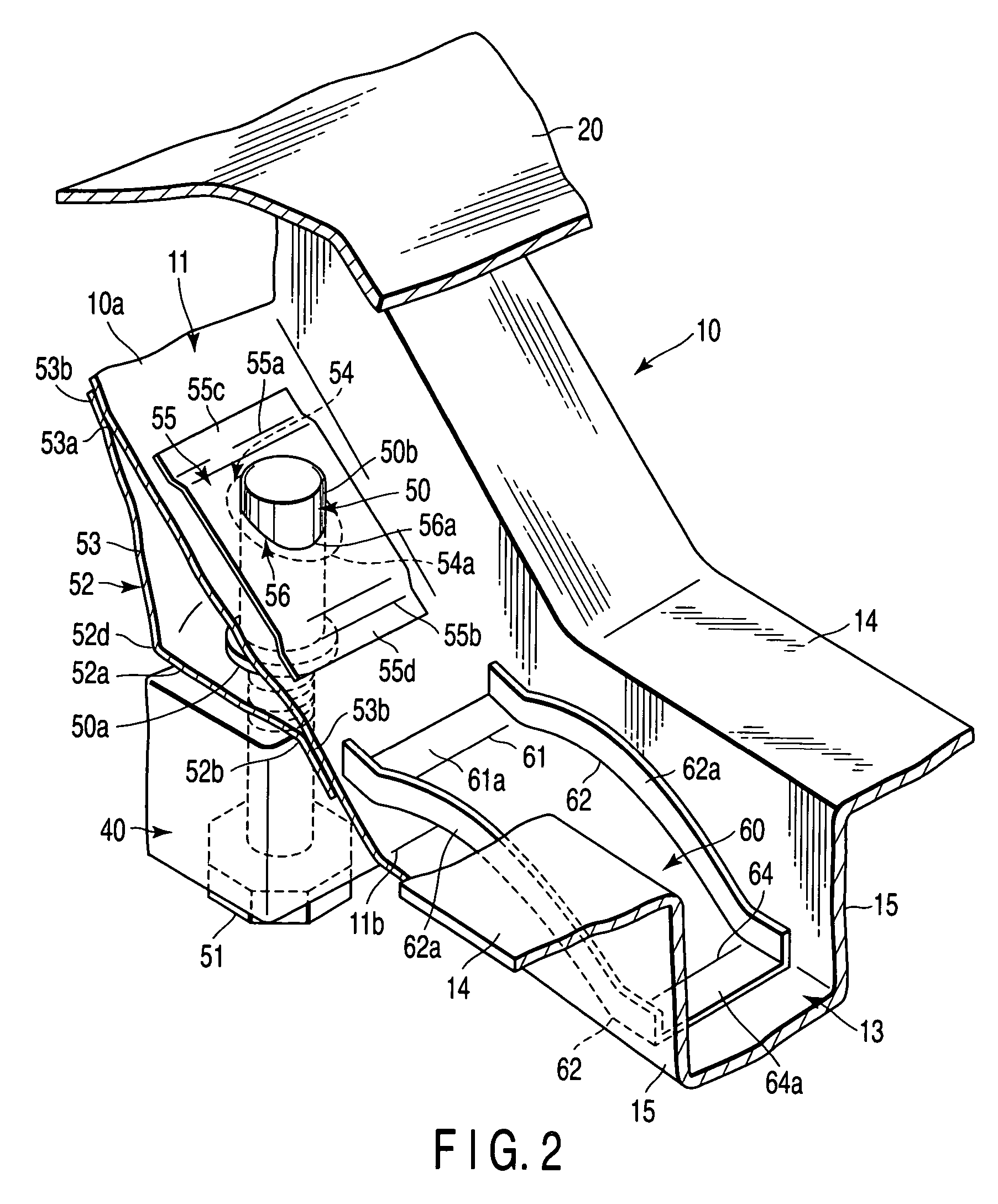
[0050]Referring first to FIGS. 1 to 8, a chassis structure for vehicles according to a first embodiment of the invention will be described.
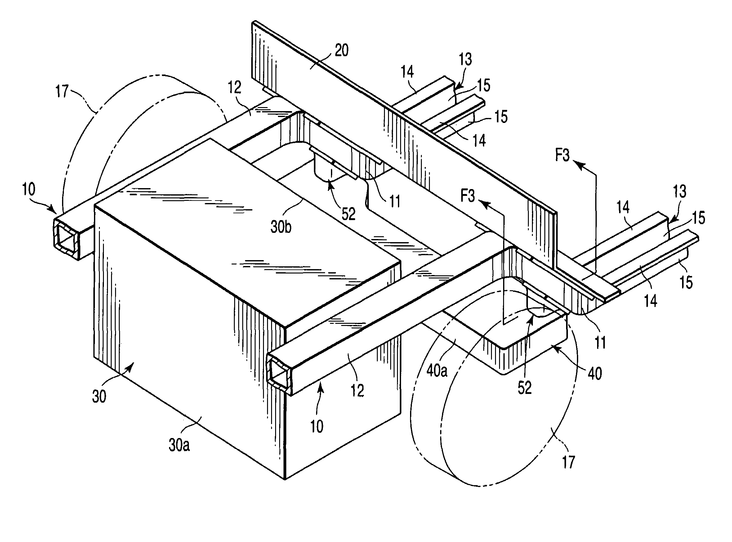
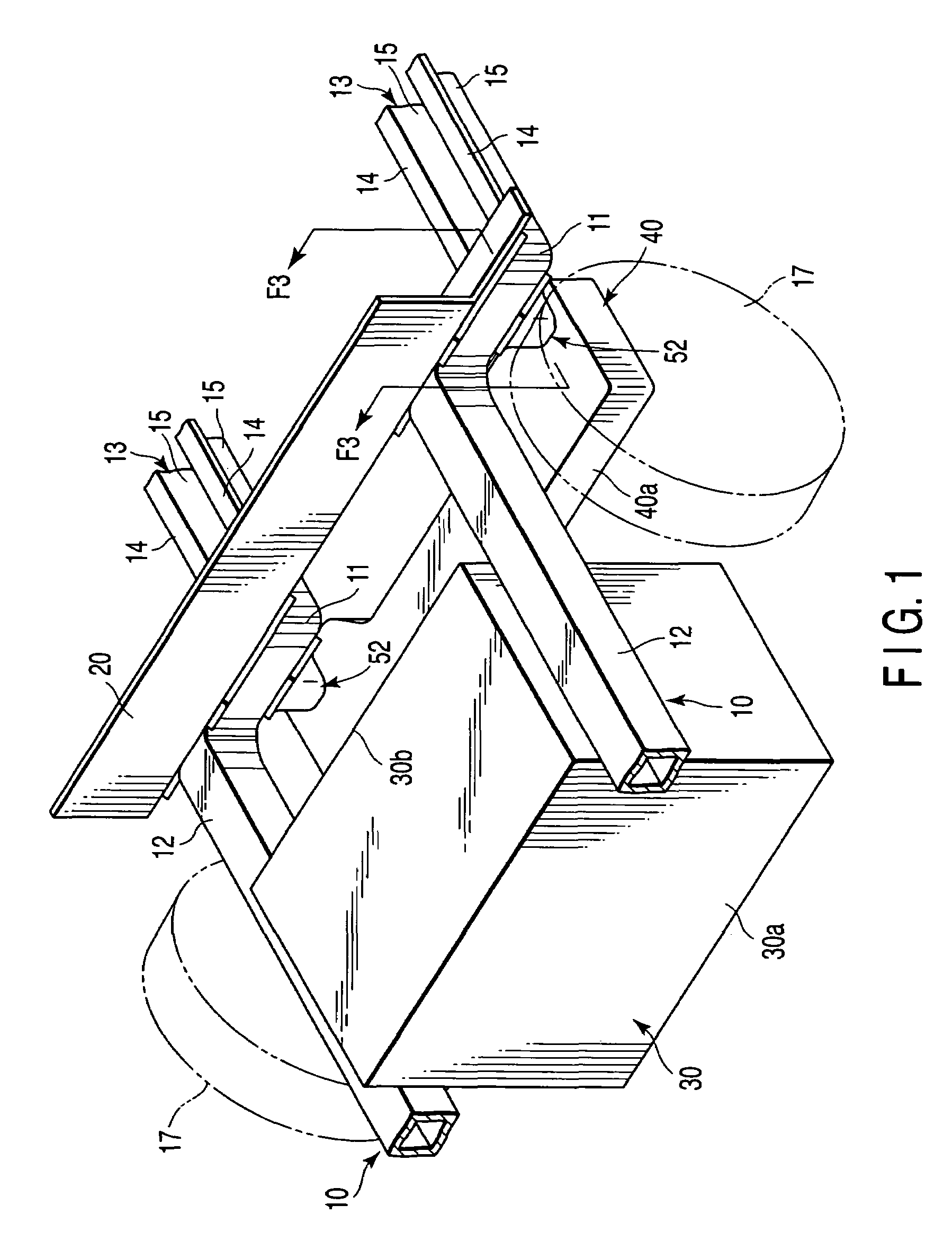
[0051]FIG. 1 shows the front portion of a chassis structure for, for example, front-engine front-wheel-drive (FF) vehicles according to the first embodiment. In FIG. 1, reference 10 denotes side members extending in the longitudinal direction of a vehicle body. A dashboard 20 is extended between and secured to the side members 10. The side members 10 each have a slanting portion 11 backwardly lowered, on which the dashboard 20 is mounted. The portion of each side member 10 located before the slanting portion 11 will hereinafter be referred to as “the front portion 12”, while the portion of each side member 10 located behind the slanting portion 11 will hereinafter be referred to as “the rear portion 13”.
[0052]The front portion 12 has, for example, a substantially rectangular cross section, and is arranged to buckle upon receiving an impact exceed...
second embodiment
[0077]FIG. 9 shows part of a chassis structure according to a second embodiment of the invention. Specifically, FIG. 9 shows a structure in which the coupling rod 50 is supported by a side member 10. The other structures are similar to those of the first embodiment, therefore no description is given thereof. Further, elements similar to those of the first embodiment are denoted by corresponding reference numerals, and are not described.
[0078]In the second embodiment, the upper portion 50b of the coupling rod 50 is supported by a second support plate 70 in the shape of a bulk head, as shown in FIG. 9. The second support plate 70 is arranged across the center of the through hole 54 in the width direction of the vehicle body, and is in contact with the upper surface of the bottom 10a of the slanting portion 11 of the side member 10, and with the inner surfaces of the side walls 15 of the side member 10. The lower end 70a of the second support plate 70 includes a flange 71 backwardly ex...
PUM
 Abstract
Description
Claims
Application Information
 - Generate Ideas
- Intellectual Property
- Life Sciences
- Materials
- Tech Scout
- Unparalleled Data Quality
- Higher Quality Content
- 60% Fewer Hallucinations
Browse by: Latest US Patents, China's latest patents, Technical Efficacy Thesaurus, Application Domain, Technology Topic, Popular Technical Reports.
© 2025 PatSnap. All rights reserved.Legal|Privacy policy|Modern Slavery Act Transparency Statement|Sitemap|About US| Contact US: help@patsnap.com


