
Catching and holding apparatus for the catching-side weft thread end in a weaving machine

a weft thread and holding technology, applied in weaving, looms, textiles and papermaking, etc., can solve the problems of increasing air consumption and correspondingly large air consumption, and achieve the effect of air consumption and air consumption

Inactive Publication Date: 2006-06-27
SULTEX AG
View PDF11 Cites 2 Cited by
  • Summary
  • Abstract
  • Description
  • Claims
  • Application Information

AI Technical Summary

Benefits of technology

[0005]An object of the invention is to make available a catching and holding apparatus for the catching-side weft thread end which reliably captures the weft thread end and holds it firmly in the catching passage with as great a force as possible, and which can be operated with an air consumption which is reduced in comparison with the prior art. A further object of the invention is to make a method available by means of which the catching-side weft thread ends are reliably captured and held firmly in the catching passage with as great a force as possible, and which manages with an air consumption which is reduced in comparison with the prior art.
[0012]With the help of the apparatus in accordance with the invention and the method in accordance with the invention, it is possible to reliably capture a weft thread with an air consumption which is reduced in comparison with the prior art. Furthermore, a specific holding and stretching force can be achieved in the apparatus in accordance with the invention with an air consumption which is reduced in comparison with the prior art. In addition it is possible to produce greater holding and stretching forces with the apparatus in accordance with the invention, which is an important advantage in particular in the case of greater weaving widths.

Problems solved by technology

In order to bring the weft thread end reliably into the catching opening, a relatively large pressure is required, which leads to a correspondingly large air consumption.
In order to achieve a sufficiently large force acting on the thread, the entry pressure must be increased correspondingly, which necessarily leads to an increased air consumption.

Method used


Image

  • Catching and holding apparatus for the catching-side weft thread end in a weaving machine
  • Catching and holding apparatus for the catching-side weft thread end in a weaving machine
  • Catching and holding apparatus for the catching-side weft thread end in a weaving machine

Examples


Embodiment Construction

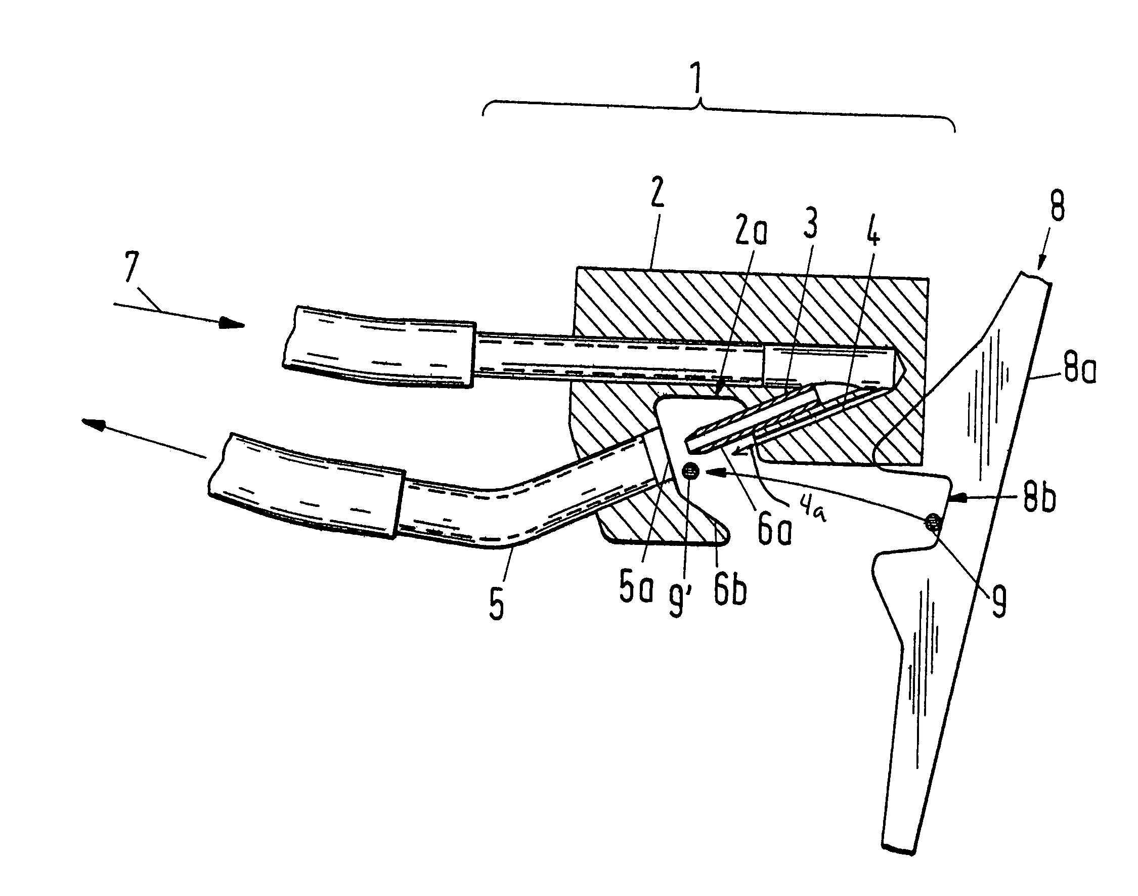
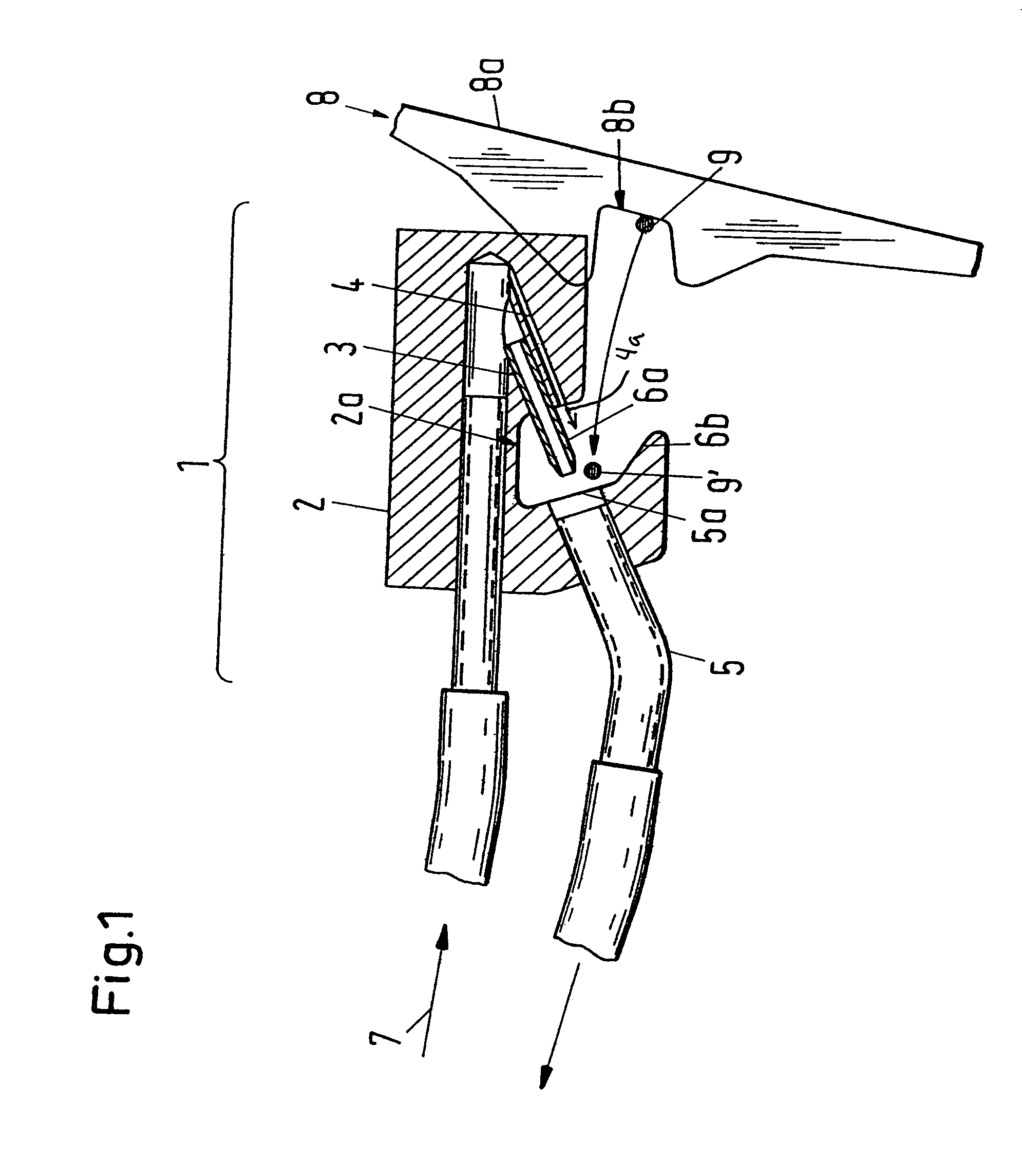
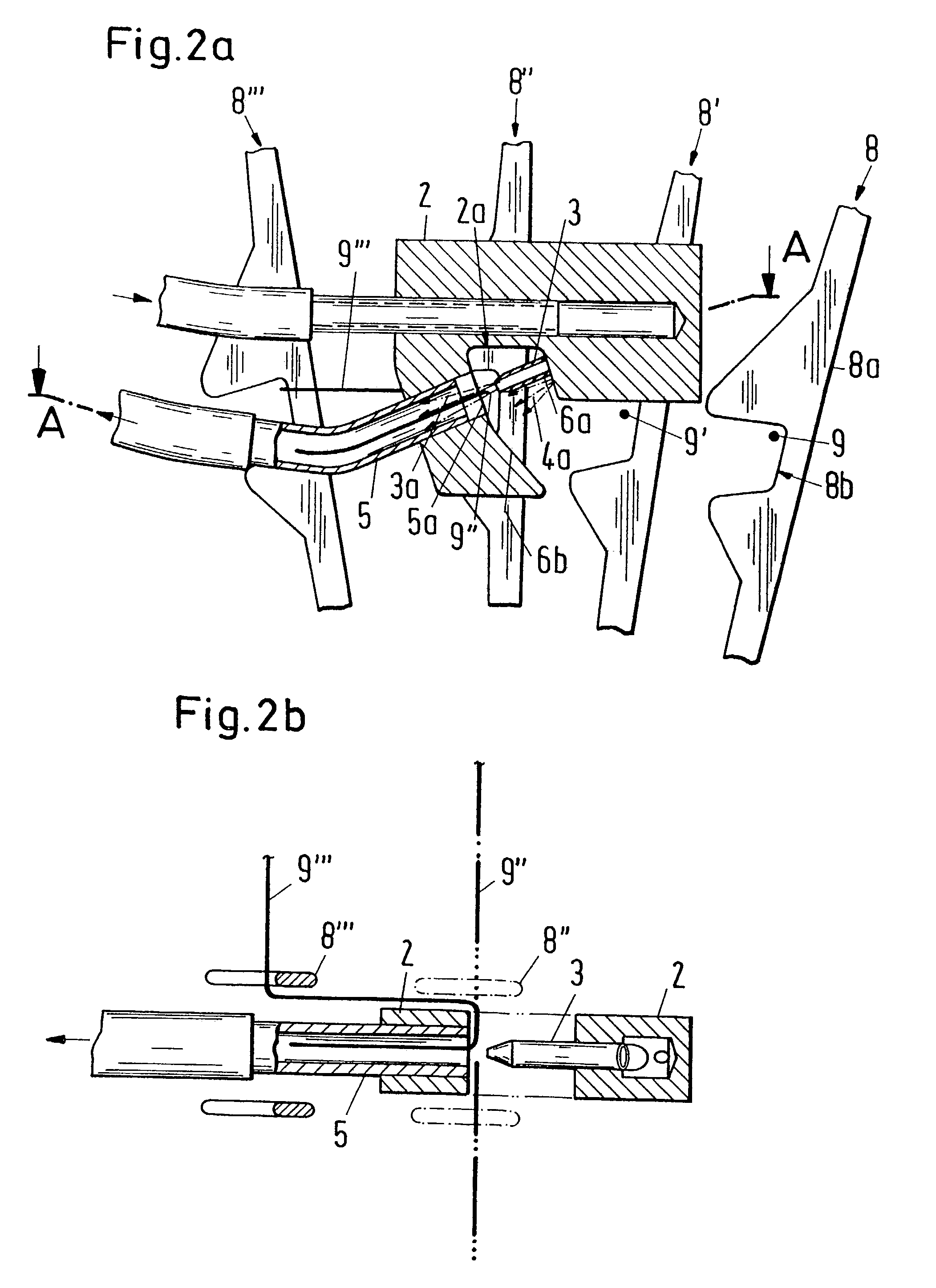
[0027]FIG. 1 shows a first exemplary embodiment pertaining to the present invention in cross-section. The catching and holding apparatus 1 of the first exemplary embodiment comprises a carrier 2 which is provided on one side with a mouth-like cut-out 2a, as well as a main nozzle 3, an auxiliary nozzle 4 and a catching passage 5, which are arranged in the carrier 2 and which open into the cut-out 2a. The main nozzle 3 in the exemplary embodiment comprises a nozzle tube, which is arranged on the one side of the cut-out 2a, and the outlet opening of which is directed towards a catching opening 5a of the catching passage 5 which is disposed on the opposite side of the cut-out 2a, with the distance between the outlet opening of the main nozzle 3 and the catching opening 5a advantageously being chosen to be less than the diameter of the catching opening 5a. The protruding part of the nozzle tube serves in the exemplary embodiment as an upper guide 6a in order to guide an inserted weft thr...


PUM


Abstract

A catching and holding apparatus for catching-side weft thread ends in a weaving machine comprises a main nozzle and a catching passage for holding and stretching a weft thread end and a carrier on which the main nozzle and the catching passage are arranged. Furthermore, the catching and holding apparatus also comprises an auxiliary nozzle and one or more guides, which are arranged on the carrier in such a manner that a weft thread end which is located in the active region of the auxiliary nozzle is brought by an air jet of the auxiliary nozzle along the guides into the active region of the main nozzle.

Description

BACKGROUND OF THE INVENTION[0001]The invention relates to a catching and holding apparatus for the catching-side weft thread end and to a weaving machine comprising a catching and holding apparatus of this kind. Furthermore, the invention relates to a method for the holding and the stretching of the weft thread end and for the transporting away of the severed weft thread end.[0002]In weaving machines, in particular air jet weaving machines, the catching-side ends of inserted weft threads are stretched and held by means of a catching and holding nozzle until the weft thread is beat up and / or the ends are severed. Conventional catching and holding nozzles are therefore frequently also designated as stretching nozzles. In a nozzle of this kind the weft thread ends are engaged by a nozzle jet and led into an opening of a catching tube or passage and held there through the air flow of the nozzle jet.[0003]In the specification of U.S. Pat. No. 4,465,110 a stretching nozzle is described wh...

Claims


Application Information

Patent Timeline
Patent Type & Authority Patents(United States)
IPC IPC(8): D03D47/30D03D41/00D03D47/48D03D49/70
CPCD03D41/005D03D49/70D03D47/48D03D47/308
Inventor SCHAICH, URS
Owner SULTEX AG
Learn More