
Method of matching a vehicle wheel

a vehicle wheel and matching technology, applied in the field of matching methods, can solve problems such as the status of tires and rims, and achieve the effects of improving the smoothness of the operation of vehicles, optimizing the index vector, and improving the operation of wheels

Active Publication Date: 2006-06-20
SNAP ON EQUIP
View PDF13 Cites 14 Cited by
  • Summary
  • Abstract
  • Description
  • Claims
  • Application Information

AI Technical Summary

Benefits of technology

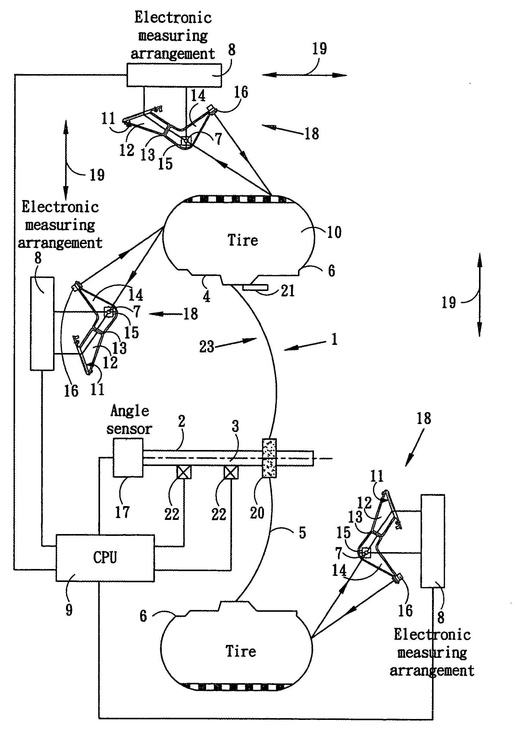
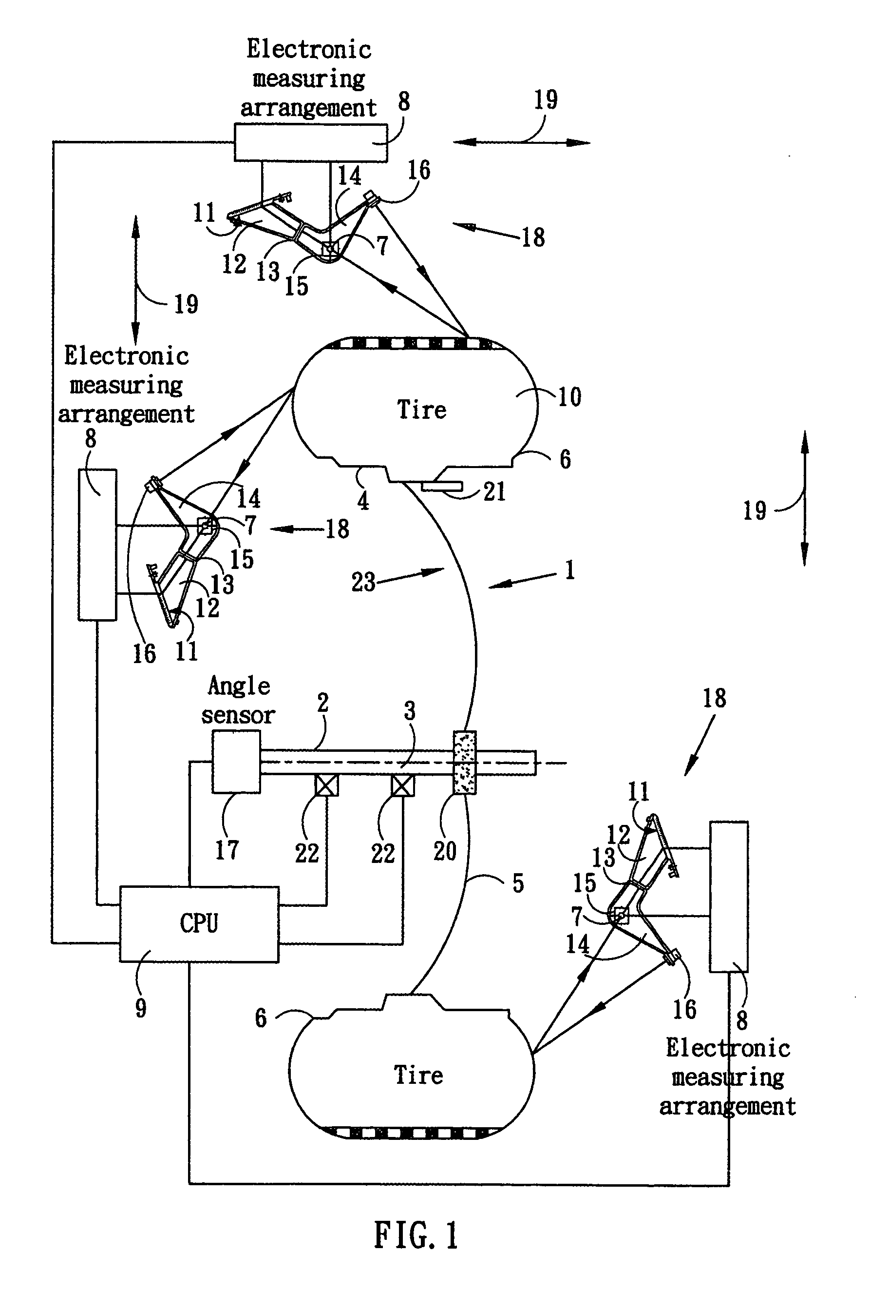
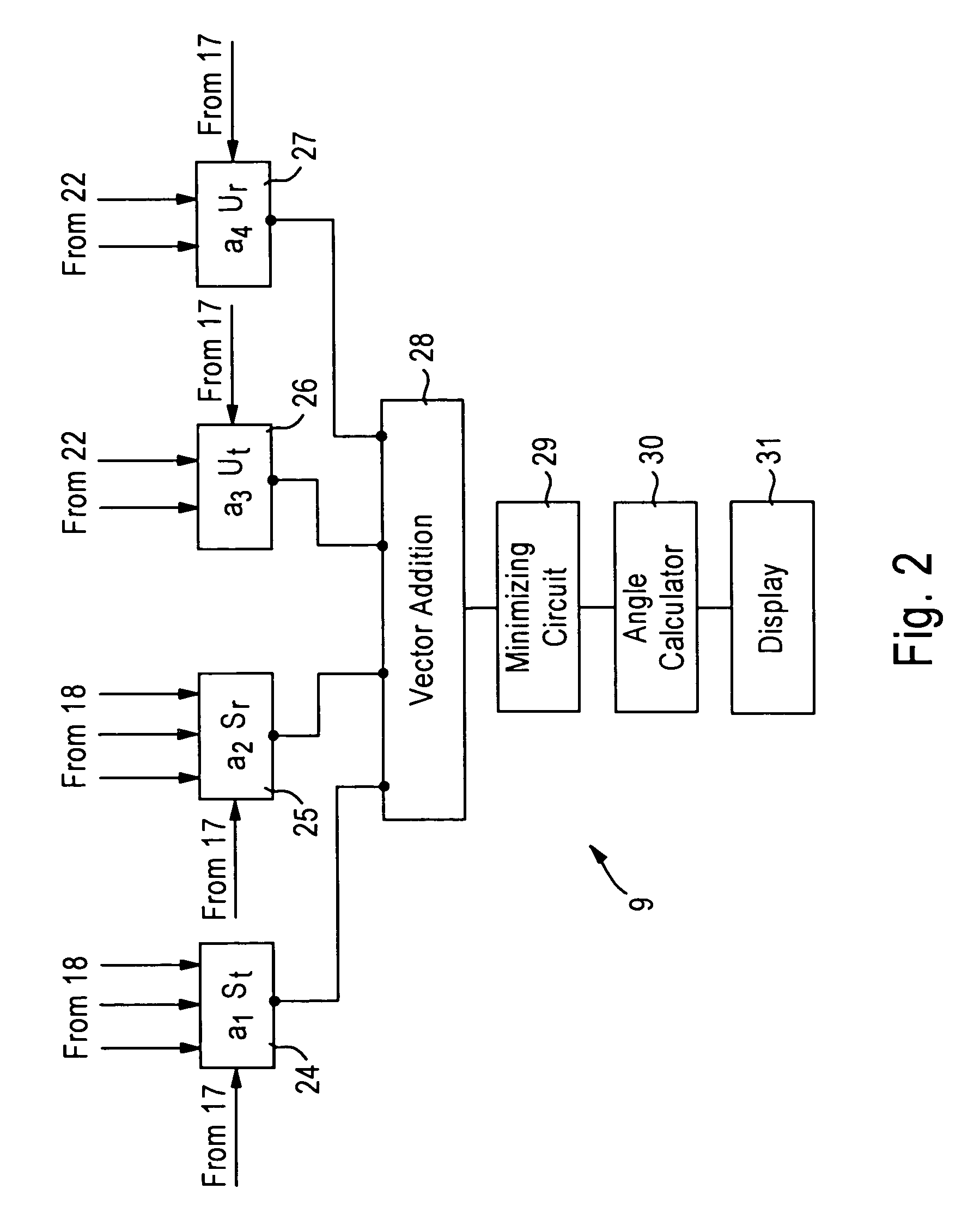
This patent describes a method for matching vehicle wheels that improves their smooth operation. The method takes into account both geometrical non-uniformities and imbalance of the wheel. An index vector is defined to measure the effects of wheel imbalance and geometrical non-uniformities, and calculations are conducted to determine an optimized position between the tire and rim that minimizes the index vector. This optimized position is then adjusted to achieve better operation of the wheel. The method can be used with different embodiments and can include measuring the geometrical parameters and imbalance status of the wheel, importing data from previous measurements, and rotating the tire to minimize the index vector.

Problems solved by technology

In addition, an imbalance measuring operation to determine the imbalance status of the tire and the rim is also carried out.

Method used


Image

  • Method of matching a vehicle wheel
  • Method of matching a vehicle wheel
  • Method of matching a vehicle wheel

Examples


Embodiment Construction

[0017]In the following description, for the purposes of explanation, numerous specific details are set forth in order to provide a thorough understanding of the present disclosure. It will be apparent, however, to one skilled in the art that the present disclosure may be practiced without these specific details. In other instances, well-known structures and devices are shown in block diagram form in order to avoid unnecessarily obscuring the present disclosure.

[0018]For illustration purpose, the following example describes an exemplary procedure for matching a wheel, which addresses the effects from both the geometrical non-uniformities and the imbalance of the vehicle wheel. In the exemplary procedure, a measuring process, such as runout measurement, is performed to obtain geometrical parameters of the wheel and the rim, and determine their respective deviations from specification values. An imbalance measuring operation is also performed to determine the imbalance status of the ti...


PUM


Abstract

A method for determining an optimized position between the tire and rim of a wheel to improve operation smoothness of the wheel. Measurements are conducted to determine respective effects of wheel imbalance and non-uniformities contributed by the tire and rim at different rotational positions. An index vector representing the respective effects is defined. The optimized position is determined based on an observation of changes of the index vector relative to the changes of respective effects of wheel imbalance and non-uniformities contributed by the tire and rim at different rotational positions. The relative position between the tire and rim is adjusted according to the optimized position to achieve better operation of the wheel.

Description

RELATED APPLICATIONS[0001]This application is related to a co-pending patent application Ser. No. 10 / 765,207, titled “METHOD AND APPARATUS FOR OPTICALLY SCANNING A PNEUMATIC TIRE OF A VEHICLE WHEEL,” filed concurrently herewith; a co-pending patent application Ser. No. 10 / 765,275, entitled “METHOD AND APPARATUS FOR BALANCING A MOTOR VEHICLE WHEEL,” filed concurrently herewith; and a co-pending patent application Ser. No. 10 / 765,274, entitled “METHOD AND APPARATUS FOR OPTICALLY SCANNING A VEHICLE WHEEL,” filed concurrently herewith. All of the applications are commonly assigned to the assignee of this application, and are incorporated herein by reference in their entireties.FIELD OF THE DISCLOSURE[0002]The present disclosure relates to a method of matching a vehicle wheel, and more specifically, to a novel wheel matching procedure that addresses effects caused by both geometrical non-uniformities and imbalance of a vehicle wheel.BACKGROUND OF THE DISCLOSURE[0003]In this disclosure, t...

Claims


Application Information

Patent Timeline
Patent Type & Authority Patents(United States)
IPC IPC(8): G06F19/00G01M1/22G01M1/32G01M1/36
CPCG01M1/225G01M1/36G01M1/326
Inventor BRAGHIROLI, FRANCESCO
Owner SNAP ON EQUIP
Learn More