
Method for sorting in a distribution order

Inactive Publication Date: 2006-06-13
SIEMENS AG
View PDF10 Cites 14 Cited by
  • Summary
  • Abstract
  • Description
  • Claims
  • Application Information

AI Technical Summary

Benefits of technology

[0013]The present invention is therefore based on an object of substantially enlarging the range of the permissible differences in the occurrence of items of mail for various distribution stopping points given identical time periods for the assignment of the sorting compartments to the distribution stopping points, without sorting compartments overflowing.

Problems solved by technology

Manually, this sorting is very complicated.
However, this reservation of overflow compartments means a reduction in the sorting capacity of the sorting machine with regard to the possible distribution stopping points.
When the sorting machine is emptied and the contents of sorting and overflow compartments are brought together, operating errors can occur which, under certain circumstances, change the order to such a great extent that repetition of the sorting becomes necessary.
The use of overflow compartments secondly does not guarantee that no further compartment-full situations can occur.
As a result, in the original compartment combination, only the remaining residual quantity is still sorted, which results in undesired nonuniform compartment filling.
Given only low levels in the sorting compartments, time losses arise, since the time expended for emptying a little-filled compartment does not differ or differs only insignificantly from emptying a full compartment.
This iterative simulation is very time-consuming, so that, in a specific time interval, only a limited difference in quantity between the distribution stopping points can be compensated for.

Method used


Image

  • Method for sorting in a distribution order
  • Method for sorting in a distribution order
  • Method for sorting in a distribution order

Examples


Embodiment Construction

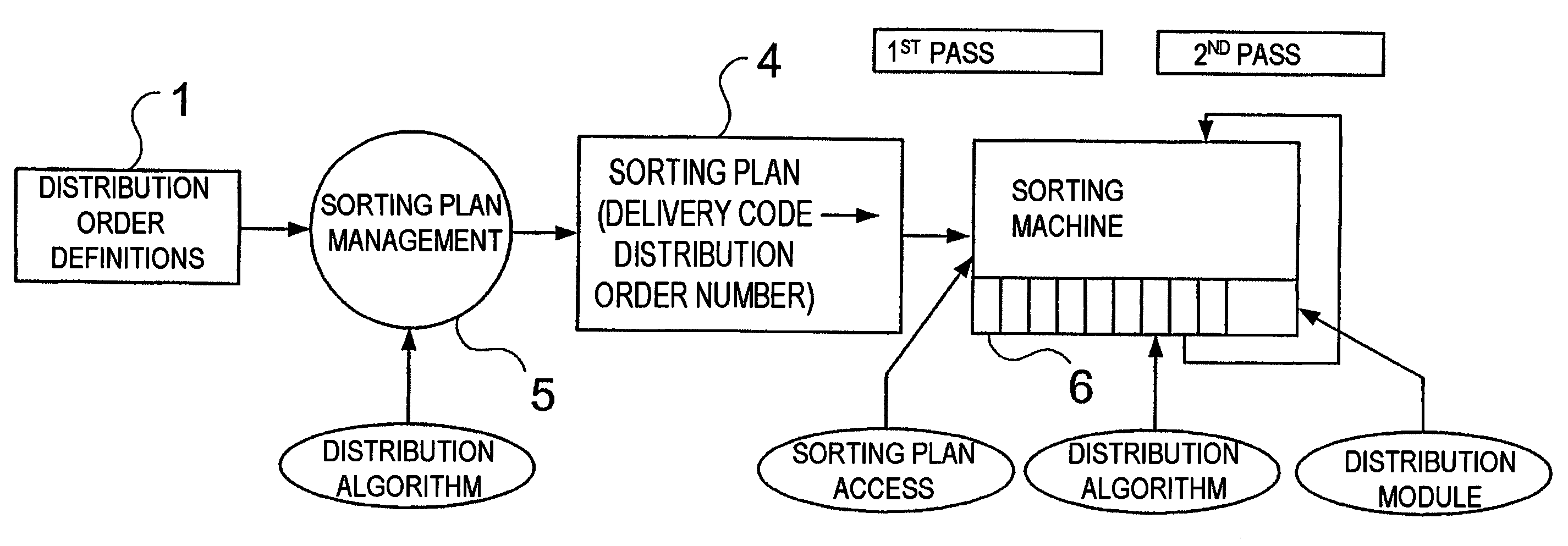
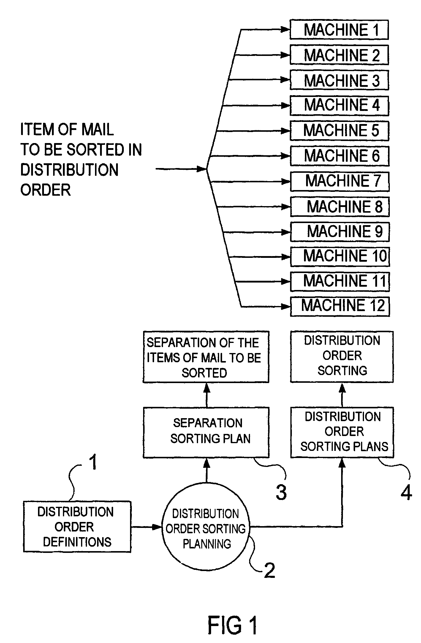
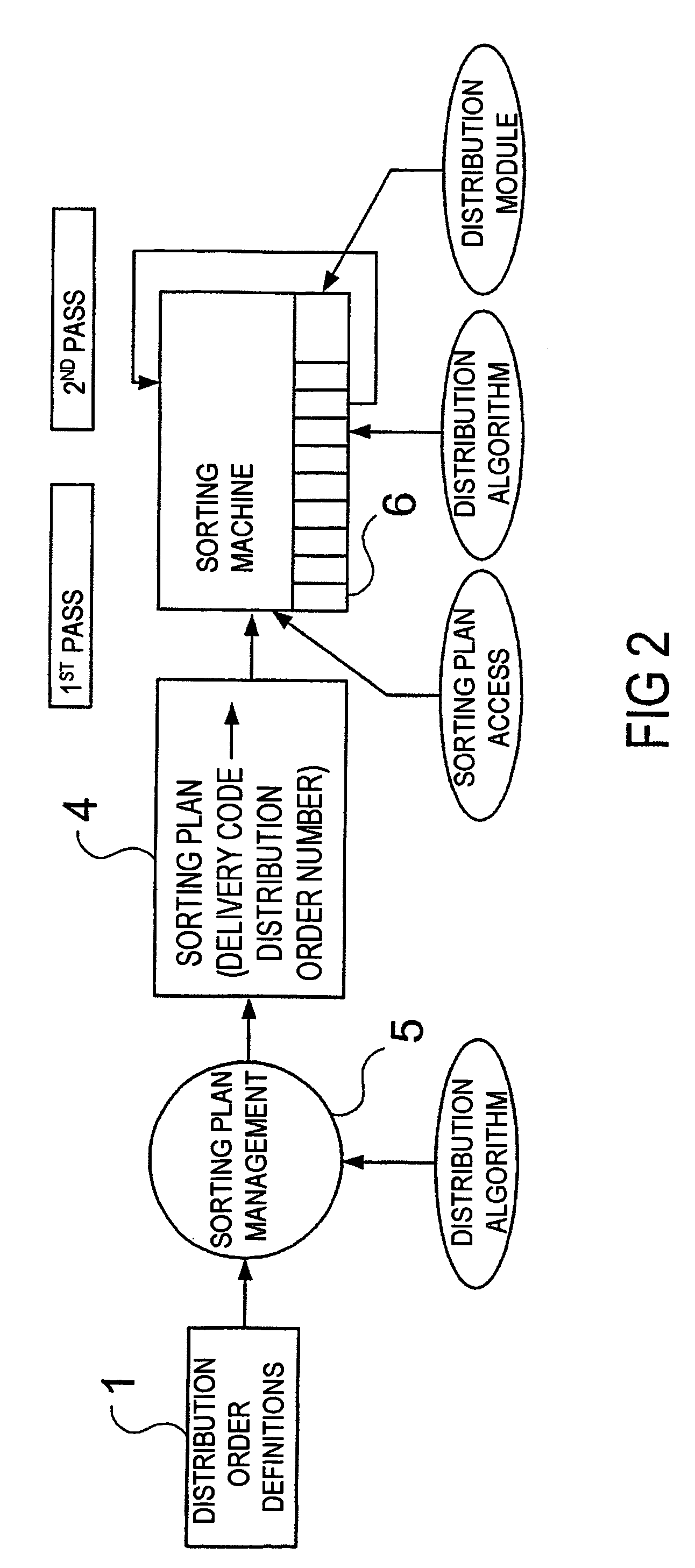
[0036]FIG. 1 depicts the starting situation of a complex sorting system. The distribution order definitions 1, called the distribution order below, are derived from a database-supported system, and contain the assignment of the destination code information to distribution order points and the quantities of items of mail to be expected per distribution order point. In the distribution order sorting planning 2, the predefined distribution orders are distributed to the available sorting machines. This planning is carried out, firstly, in accordance with logical criteria set by the operator, secondly in accordance with loading criteria of the machines. In practice, this means that the planner attempts to match the logistical criteria of the operator to the existing machine park and, for this purpose, needs a tool which, during the planning, can continuously check whether the capacity limit of one or more machines has already been reached or not. The result of this planning are the distr...


PUM


Abstract

In the present invention a sorting machine in a distribution order is made to process a substantially higher number of distribution order points, within a sorting process, than necessary for sorting in one or several real distribution orders based on the available pigeon holes. Real distribution order points with large quantities of mailing pieces are distributed between several virtual distribution order points with a minimum quantity of mailing pieces. The quantity of mailing pieces statistically determined for each real distribution order point of a defined distribution order are distributed between the virtual distribution order points, as regularly as possible, for the sorting passes preceding the final sorting pass. Then, the sorting passes preceding the final sorting pass are executed. The final sorting pass is thus executed, such that the mailing pieces of a distribution order are sorted into adjacent pigeon holes.

Description

CROSS REFERENCE TO RELATED APPLICATIONS[0001]The present application is a continuation of international application PCT / DE02 / 03247, filed Mar. 9, 2002 and further claims priority to German patent application DE10145295.0, filed Sep. 14, 2001, the both of which are herein incorporated by reference.BACKGROUND OF THE INVENTION[0002]Sorting items of mail in a distribution order is understood to mean the procedure of bringing the items of mail to be distributed into an order which corresponds to the order of the distribution stopping points, for example in accordance with house numbers / mailboxes. These distribution stopping points are walked to or driven to by the distributor systematically in his delivery area. The distribution stopping point is in this case not an absolute sorting destination but a relative position in the distribution order.[0003]Manually, this sorting is very complicated. By means of a sorting machine, this sorting can be carried out with considerably less expenditur...

Claims


Application Information

Patent Timeline
IPC IPC(8): B07C5/00B07C3/18B07C3/00
CPCB07C3/00Y10S209/90
Inventor JIRSA, REINHARD
Owner SIEMENS AG
Learn More