
Electrical connector and backshell

a backshell and connector technology, applied in the direction of electrical apparatus, connection, coupling device connection, etc., can solve the problems of troublesome handling of two parts and relatively high manufacturing cos

Active Publication Date: 2006-06-13
TYCO ELECTRONICS LOGISTICS AG (CH)
View PDF6 Cites 80 Cited by
  • Summary
  • Abstract
  • Description
  • Claims
  • Application Information

AI Technical Summary

Problems solved by technology

Particularly in circular connectors, where cabling and harness work must be performed, these two parts can become troublesome to handle and may be relatively expensive to manufacture.

Method used


Image

  • Electrical connector and backshell
  • Electrical connector and backshell
  • Electrical connector and backshell

Examples


Embodiment Construction

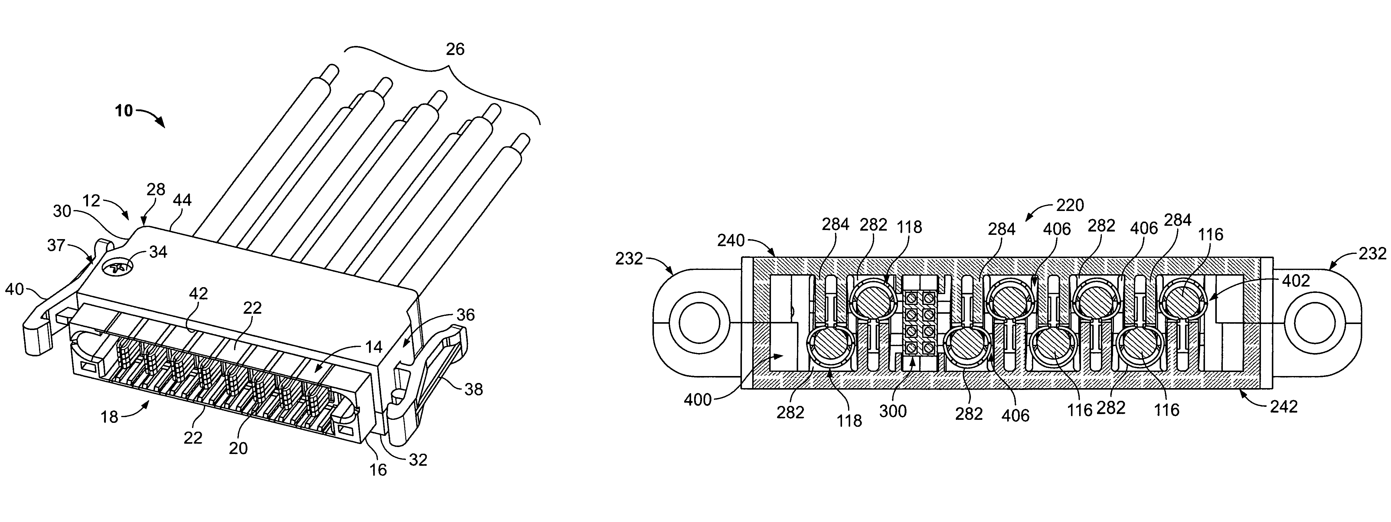
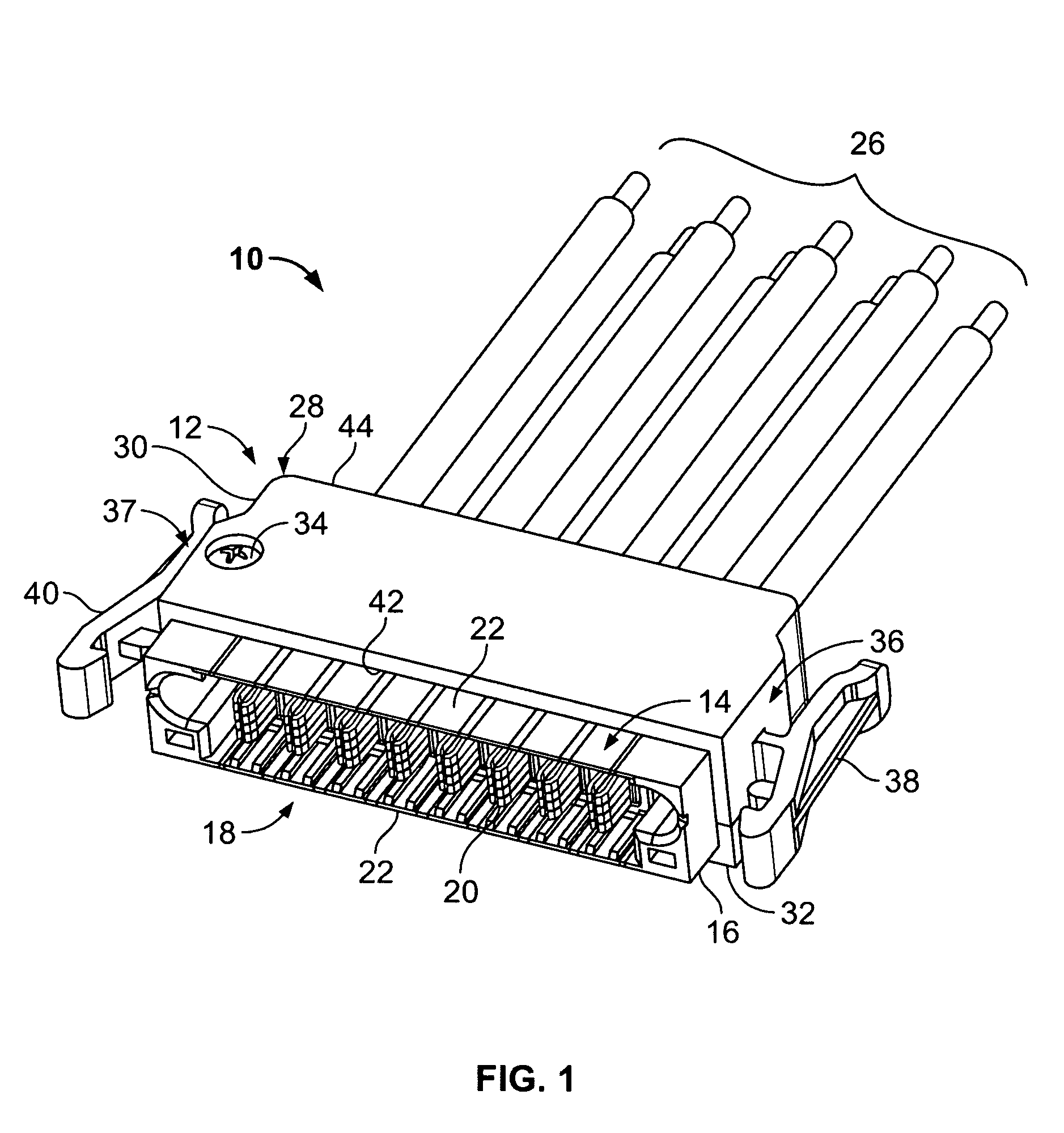
[0023]FIG. 1 is perspective view of a connector and backshell assembly 10 formed according to an embodiment of the present invention. While the connector and backshell assembly 10 will be described with particular reference to a header connector, it is to be understood that the benefits herein described are also applicable to other connectors in alternative embodiments. The following description is therefore provided for purposes of illustration, rather than limitation, and is but one potential application of the inventive concepts herein.

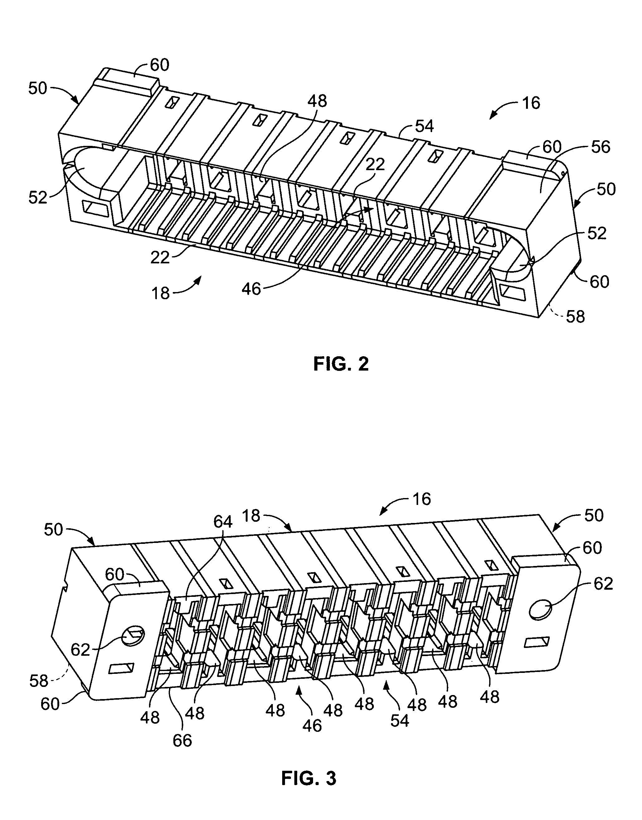
[0024]The assembly 10 includes a backshell 12 and a connector 14. In an exemplary embodiment, the connector 14 is a header or plug connector. The connector 14 includes a housing 16 formed from a dielectric material. The housing 16 includes a forward mating face 18. A plurality of contacts 20 are surrounded by a shroud 22 at the mating face 18 of the connector 16. The contacts 20 are joined to a plurality of cables 26 that extend from a cable exit e...


PUM


Abstract

An electrical connector assembly includes a connector housing holding a plurality of electrical contacts and a backshell including a backshell housing having a connector receiving end and a cable exit end. The connector housing is coupled to the connector receiving end of the backshell housing. A plurality of organizing elements are within the backshell housing. The organizing elements are arranged in a transverse row within the backshell housing. The organizing elements are configured to receive and support a plurality of electrical cables arranged in first and second transverse rows. The first and second rows are in a tiered relationship with one another and the electrical cables are transversely offset from one another.

Description

BACKGROUND OF THE INVENTION[0001]The invention relates generally to electrical connectors, and more particularly, to a connector and backshell assembly.[0002]In general, an electrical cable includes one or more conductors, which may be wire conductors, that are surrounded by an insulation layer. Networked electronic systems often include a number of devices communicating with other devices through a number of associated electrical cables with electrical connectors. Typically, one device is connected to another device or system through a single conductor or multiple conductors that are terminated with contacts in a connector housing. To terminate the conductors to the connector contacts, wire insulation is removed from an end of the cable to expose the conductors therein. The conductors are placed into the contacts of the connector and the conductors are attached thereto, such as with crimping or soldering techniques.[0003]It is common to utilize a backshell on an electrical connecto...

Claims


Application Information

Patent Timeline
Patent Type & Authority Patents(United States)
IPC IPC(8): H01R13/58
CPCH01R13/5812Y10S439/942
Inventor TROUT, DAVID ALLISON
Owner TYCO ELECTRONICS LOGISTICS AG (CH)
Learn More