Eureka AIR delivers breakthrough ideas for toughest innovation challenges, trusted by R&D personnel around the world.

Motors with oil dynamic pressure bearing, oil dynamic pressure bearing devices and method for manufacturing the same

a technology of dynamic pressure bearing and oil dynamic pressure, which is applied in the direction of sliding contact bearings, mechanical equipment, dynamo-electric components, etc., can solve the problems of increasing the number of hard disks, the amount of lubricating oil retained is small, and the rotational speed and rotational precision of disks are concomitantly on the ris

Inactive Publication Date: 2006-06-13
NIDEC CORP
View PDF2 Cites 13 Cited by
  • Summary
  • Abstract
  • Description
  • Claims
  • Application Information

AI Technical Summary

Benefits of technology

[0031]In addition, the present invention also relates to an oil dynamic pressure bearing apparatus, and its manufacturing method, in which the span in the axial direction to form radial dynamic pressure bearings can be lengthened, the rigidity of the radial dynamic pressure bearings can be enhanced, the joining area between a cover that closes an opening at one end of the dynamic pressure bearing member and the dynamic pressure bearing member can be increased, and the joining strength between the two enhanced.
[0034]In another aspect of the present embodiment, lubricating oil is filled in the radial dynamic pressure bearings and the thrust dynamic pressure bearing; a tapered section is provided more on the outer side in the axial direction than the thrust dynamic pressure bearing, wherein the dimension of the tapered section between the outer circumference surface of the dynamic pressure bearing member and the opposing inner circumference surface of the fallout preventing member gradually expands towards the outer side in the axial direction, and the tapered section defines a capillary sealing section that prevents the lubricating oil from leaking and that consist of the tapered section.

Problems solved by technology

For example, in hard disk drive apparatuses, the recording density of hard disks is increasing rapidly, and the rotational speed and rotational precision of disks are concomitantly on the rise.
The example in FIG. 12 amply provides for a joining length between a rotary shaft 16 and a rotary member 20 and the joining length L of the joining section between the dynamic pressure bearing member 14 and the base plate 10, but the thickness of the fallout preventing member 30 and the length of the capillary sealing section 32 are insufficient; consequently, the amount of lubricating oil retained is small and there is a risk of shortening the life of the motor as a result of the evaporation of the lubricating oil.
Furthermore, the joining strength between the base plate 10 and the dynamic pressure bearing member 14 is also insufficient.
When an attempt is made to realize such an oil dynamic pressure bearing motor, whose height dimension is extremely limited, using structures indicated in FIG. 11 or 12, problems described below can occur.
In the case of a disk drive motor, a disk mounting surface swings and causes the disk to undulate as it rotates, such that the disk vibrates, or the flow of air generated by the rotation of the disk becomes disrupted.
Any of these can cause the head to fail to levitate above the disk by a predetermined amount and / or tracks to be displaced and error rate during data reproduction to be increased.
Further, due to the fact that the back surface of the rotary member 20 is a thrust bearing surface, if the perpendicularity of the rotary shaft 16 with the rotary member 20 is poor, the number of revolutions for levitation, i.e., the number of revolutions required to obtain predetermined levitating force in the thrust direction, increases, such that the amount of time the rotary member 20 is in contact with the dynamic pressure bearing member 14 becomes longer, which causes greater bearing wear and therefore lower reliability of the bearing.
However, due to the fact that the outer circumference surface of the cover 22 and the outer circumferential wall surface of the ring-shaped circumferential groove 76 formed on one end surface of the dynamic pressure bearing member 14 are joining surfaces, sufficient adhesive cannot be coated on or filled in between the dynamic pressure bearing member 14 and the cover 22; this results in insufficient reliability for a sealing means of the opening.
Furthermore, a large space formed between the circumferential wall 221 of the cover 22 and the wall surface on the inner circumference side of the circumferential groove 76 must be filled with dynamic pressure generating lubricating oil, which requires a long time and leads to lower productivity.
Moreover, parts that are filled with a large amount of the lubricating oil tend to have air bubbles in the lubricating oil, which can cause the lubricating oil to be more prone to leaking.

Method used


Image

  • Motors with oil dynamic pressure bearing, oil dynamic pressure bearing devices and method for manufacturing the same
  • Motors with oil dynamic pressure bearing, oil dynamic pressure bearing devices and method for manufacturing the same
  • Motors with oil dynamic pressure bearing, oil dynamic pressure bearing devices and method for manufacturing the same

Examples


Embodiment Construction

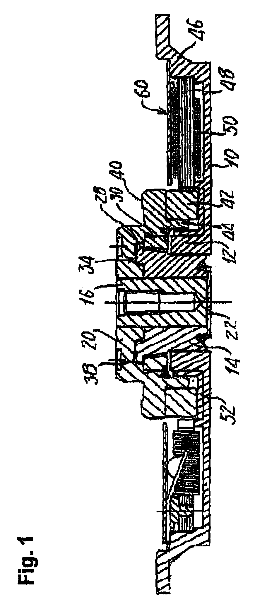
[0061]An oil dynamic pressure bearing motor, an oil dynamic pressure bearing apparatus and its manufacturing method in accordance with embodiments of the present invention are described below with references to the accompanying drawings. The oil dynamic pressure bearing motor according to an embodiment is structured as a disk drive apparatus that rotatively drives disks such as hard disks, but the oil dynamic pressure bearing motor according to the present invention is applicable as dynamic pressure bearing apparatuses for various equipment other than disk drive apparatuses, Like components as those in the examples shown in FIGS. 11 and 12 are assigned the same numbers.

[0062]In FIGS. 1 and 2, an oil dynamic pressure bearing motor includes a rotary shaft 16 and a dynamic pressure bearing member 14. The dynamic pressure bearing member 14 is generally cylindrical, and the rotary shaft 16 is fitted into its center hole with a miniscule gap between the two members. A rotary member 20 is ...


PUM


Abstract

A motor with fluid dynamic pressure bearing is disclosed. The motor includes a dynamic pressure bearing member having a concave section that is concave in an axial direction, a rotary shaft that is rotatively supported by the dynamic pressure bearing, and a rotary member that is joined to the rotary shaft in one piece along a joint section between the rotary member and the rotary shaft, and rotatively driven by electromagnetic drive force, an expanded diameter section that is provided on the dynamic pressure bearing member. A fallout preventing member is provided on the rotary member, which overlaps the expanded diameter section of the dynamic pressure bearing member in the axial direction to prevent the rotary shaft from falling out of the dynamic pressure bearing member. The concave section of the rotary member opposes in the axial direction the expanded diameter section of the dynamic pressure bearing member, wherein the expanded diameter section is placed inside the concave section, and the joining section between the rotary member and the rotary shaft overlaps the expanded diameter section in the radial direction.

Description

BACKGROUND OF THE INVENTION[0001]1. Field of the Invention[0002]The present invention relates to motors with oil dynamic pressure bearings, which are equipped with a rotary shaft and a dynamic pressure bearing member in which the rotary shaft rotates relatively to the dynamic pressure bearing member in a non-contact manner, oil dynamic pressure bearing devices and method for manufacturing the same. The present invention also relates to motors with oil dynamic pressure bearing and oil dynamic pressure bearing devices, which can be used for disk drive motors for magnetic disks, optical disks or the like, as well as drive motors of a variety of apparatuses for which high rotational precision is demanded.[0003]2. Related Background Art[0004]Motors with oil dynamic pressure bearing (hereafter referred to as “oil dynamic pressure bearing motors”) are used as drive motors for various apparatuses for which high rotational precision is demanded. For example, in hard disk drive apparatuses, t...

Claims


Application Information

Patent Timeline
Patent Type & Authority Patents(United States)
IPC IPC(8): F16C17/10F16C33/10F16C33/72H02K5/16
CPCF16C33/723H02K5/1675F16C43/02F16C17/107F16C33/745F16C2370/12
Inventor GOMYO, MASATOASHIBE, NOBORUSUGINOBU, SHINGO
Owner NIDEC CORP
Why Eureka
Eureka Blog
Learn More