Apparatus and method for observing chemical substances

a chemical substance and apparatus technology, applied in the field of methods and apparatuses for observing chemical substances and processes, can solve the problems of distorted view of the chemical solution in the flask, difficulty in accurately and consistently determining the end point of the target chemical, and inability to achieve consistent or repeatable titration by practitioners

Inactive Publication Date: 2006-06-13
MICRON TECH INC
View PDF27 Cites 7 Cited by
  • Summary
  • Abstract
  • Description
  • Claims
  • Application Information

AI Technical Summary

Problems solved by technology

Accordingly, a drawback with this technique is that it can be difficult to accurately and consistently determine the end point of the target chemical, particularly if the practitioner fails to observe the initial color change.
However, this approach can have several additional drawbacks.
For example, if the practitioner uses a slightly differently colored background material for successive titrations, the practitioner may not achieve consistent or repeatable titration results.
Furthermore, the practitioner may wish to move the flask to achieve an optimal viewing angle, which can be awkward if the practitioner must also move a piece of paper or paper towel held against a surface of the flask.
Still further, the practitioner's view of the chemical solution in the flask may be distorted by the curvature of the flask at the juncture between the bottom of the flask and the walls of the flask, particularly when the volume of the chemical in the flask is relatively small.

Method used


Image

  • Apparatus and method for observing chemical substances
  • Apparatus and method for observing chemical substances
  • Apparatus and method for observing chemical substances

Examples


Embodiment Construction

[0014]The present disclosure describes vessels for supporting chemical substances and methods for making and using such vessels. Many specific details of certain embodiments of the invention are set forth in the following description and in FIGS. 1–5 to provide a thorough understanding of these embodiments. One skilled in the art, however, will understand that the present invention may have several additional embodiments, or that the invention may be practiced without several of the details described below.

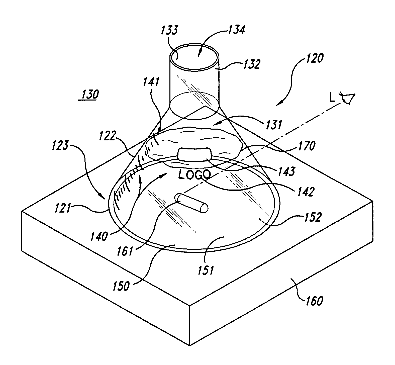
[0015]FIG. 1 is a top isometric view of a vessel 120 having a fixedly attached background material 150 in accordance with an embodiment of the invention. In one aspect of this embodiment, the vessel 120 includes a generally flat base portion 121 connected to an upwardly extending wall portion 122 at an interface region 123. In a further aspect of this embodiment, the base portion 121, the wall portion 122 and the interface region 123 can be integrally formed with each other. Alter...


PUM

PropertyMeasurementUnit
chemicalaaaaaaaaaa
hueaaaaaaaaaa
whiteaaaaaaaaaa

Abstract

An apparatus and method for observing a chemical substance. In one embodiment, the apparatus includes a vessel having a base portion and an at least partially transparent wall portion depending from and extending away from the base portion. The base portion and the wall portion define an interface region at an interface between the base portion and the wall portion. The vessel can further include a background material fixedly attached to the base portion and/or the interface region, with the background material having a surface visible through the wall portion from a region exterior to the vessel. The background material can be attached to an inner surface or an outer surface of the vessel, or the background material can be integrated with a medium that forms the base portion and the wall portion of the vessel. The background material can have a single color, such as white or black, or the background material can have a plurality of hues to make the contents of the vessel more clearly visible.

Description

TECHNICAL FIELD[0001]The present invention is directed to methods and apparatuses for observing chemical substances and processes, such as liquid chemical titrations.BACKGROUND OF THE INVENTION[0002]Many chemistry practitioners rely on visual observations to determine when chemical processes and reactions are complete. For example, one conventional technique for determining the concentration of an acid is to titrate the acid by adding a basic solution of a known concentration to the acid until the endpoint is achieved. When the acid / base solution reaches the end point (i.e., the point at which the exact amount of necessary base has been added to completely react with the acid), the color of a chemical indicator in the acid / base solution changes. The practitioner can then calculate the concentration of the acid by measuring the quantity of the base that was required to reach the end point.[0003]One characteristic feature of the technique described above is that the chemical indicator...

Claims


Application Information

Patent Timeline
Patent Type & Authority Patents(United States)
IPC IPC(8): B65D25/54B01L3/00B01L3/08G01N21/79
CPCB01L3/08B01L3/508G01N21/79B01L2300/168B01L2200/14
Inventor SMITH, GEORGE E.
Owner MICRON TECH INC
Why Eureka
Try Eureka