
Transforming a digital image from a low dynamic range (LDR) image to a high dynamic range (HDR) image

a digital image and high dynamic range technology, applied in image enhancement, color signal processing circuits, instruments, etc., can solve the problems of loss of details, limited use of hdri displays, and introduction of noise in the region of high luminan

Active Publication Date: 2012-08-09
IBM CORP
View PDF9 Cites 98 Cited by
  • Summary
  • Abstract
  • Description
  • Claims
  • Application Information

AI Technical Summary

Benefits of technology

[0002]The present invention generally relates to image processing and more specifically to a method and system for transforming a digital image from a Low Dynamic Range (LDR) image to a High Dynamic Range (HDR) image.
[0012]FIG. 3 shows an exemplary camera response curve;
[0013]FIG. 4 depicts the inverse response curve obtained from the camera response curve of FIG. 3, in accordance with embodiments of the present invention;
[0068]With the invention, new HDR displays can be used for viewing existing LDR images in many applications, such as medical imaging.
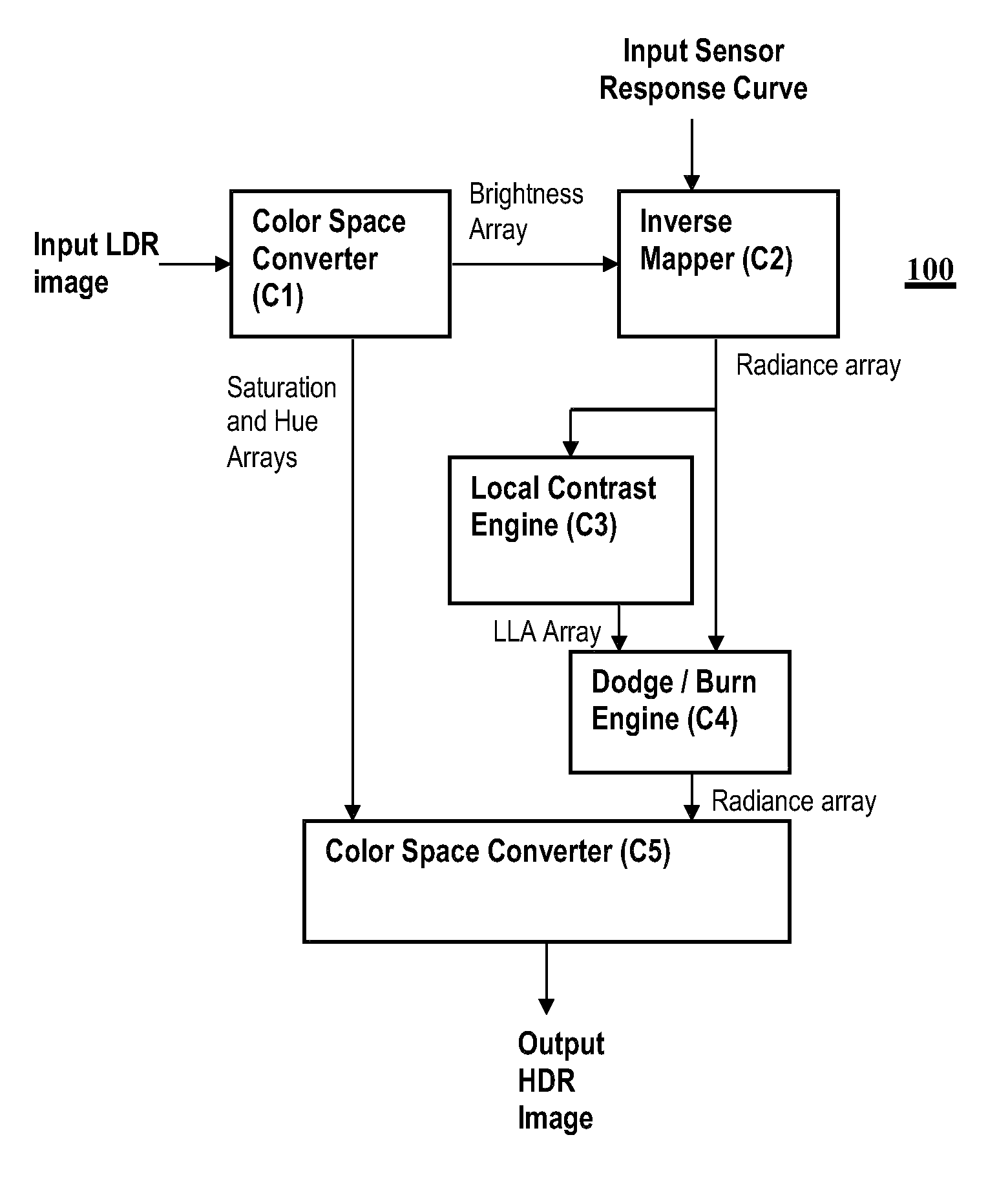
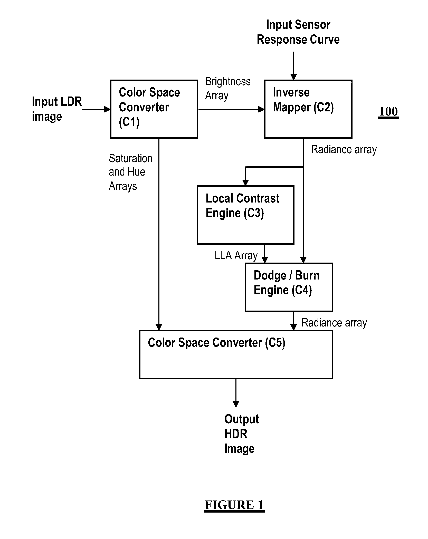
[0022]In general, an improved reverse tone mapping for transforming an LDR image into an HDR image is provided. The camera response curve is used to reconstruct the radiance map of the image, instead of performing inverse gamma or standard fixed inverse function as provided in the prior art solutions.

Problems solved by technology

However, since the existing media is not of High Dynamic Range (HDR), the utility of HDRI displays is limited to newly acquired HDR images using HDRI sensors.
Due to image quantization, this phase results in loss of details and introduces noise in the region of high luminance.
However, these existing solutions provide an inverse tone mapping function for the first phase that is not accurate enough.
However, such extrapolation only happens to extend the luminance of the hotspots (highlights) and nearby regions, and never decrease the luminance in dark regions (shades).

Method used


Image

  • Transforming a digital image from a low dynamic range (LDR) image to a high dynamic range (HDR) image
  • Transforming a digital image from a low dynamic range (LDR) image to a high dynamic range (HDR) image
  • Transforming a digital image from a low dynamic range (LDR) image to a high dynamic range (HDR) image

Examples


Embodiment Construction

[0022]In general, an improved reverse tone mapping for transforming an LDR image into an HDR image is provided. The camera response curve is used to reconstruct the radiance map of the image, instead of performing inverse gamma or standard fixed inverse function as provided in the prior art solutions.

[0023]Certain aspects rely upon dodging and burning operations to selectively increase the luminance or decrease the luminance of an image, respectively. A dodging and burning like operation is applied in the HDR domain to extend the dynamic range of an image. This also generally expands the local contrast allowing for more visible details that are not visible in the LDR image. Moreover, applying a dodging and burning like operation in the HDR domain allows for performing smoothing, thereby decreasing the quantization effects.

[0024]Advantages include but are not limited to the following: (i) a simplified technique to perform recovering of HDR values from a single LDR image, which is eas...


PUM


Abstract

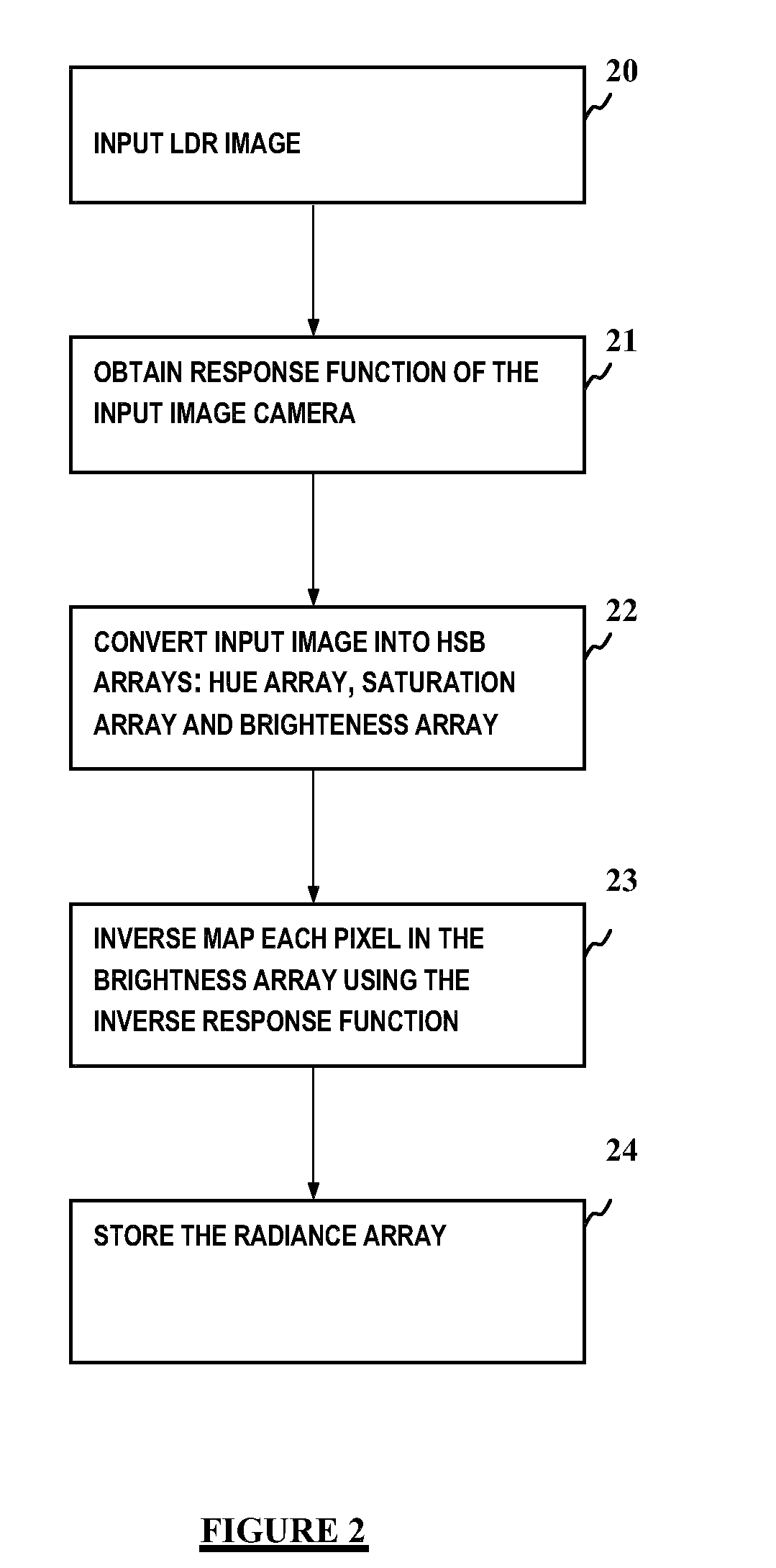
The invention provides a method for transforming an image from a Low Dynamic Range (LDR) image obtained with a given camera to a High Dynamic Range (HDR) image, the method comprising:obtaining the exposure-pixel response curve (21) for said given cameraconverting the LDR image to HSB color space arrays (22), said HSB color space arrays including a Hue array, a Saturation array and a Brigthness array; anddetermining a Radiance array (23, 24) by inverse mapping each pixel in said Brightness array using the inverse of the exposure-pixel response curve (f-1).

Description

CROSS-REFERENCE TO RELATED APPLICATIONS[0001]This application is a national stage of PCT / EP2010 / 059950 filed Jul. 12, 2010, designating, inter alia, the United States and claiming priority to European Patent Application No. 09172538.2 filed Oct. 8, 2009, each of which is hereby incorporated by reference in their entirety.FIELD OF THE INVENTION[0002]The present invention generally relates to image processing and more specifically to a method and system for transforming a digital image from a Low Dynamic Range (LDR) image to a High Dynamic Range (HDR) image.BACKGROUND OF THE INVENTION[0003]An emerging technology in the field of digital photography is High Dynamic Range Imaging (HDRI). HDRI provides for capturing most of actual world luminance, making it possible to reproduce a picture as close as possible to reality when using appropriate displays. High dynamic range imaging thus provides a representation of scenes with values commensurating with real-world light levels. The real worl...

Claims


Application Information

Patent Timeline
IPC IPC(8): G06K9/32
CPCG06T5/009G06T2200/21G06T2207/20208H04N5/20H04N19/14H04N5/2351H04N5/2355H04N9/67H04N5/23229H04N23/80H04N23/71H04N23/741G06T5/92
Inventor EL-MAHDY, AHMED H.EL-SHISHINY, HISHAM E.
Owner IBM CORP
Learn More