
Method and system for representing a virtual object in a view of a real environment

a virtual object and environment technology, applied in the field of methods and systems for representing virtual objects in the view of the real environment, can solve the problems of limiting the applicability of these approaches, affecting the reliability of the simulation, and unable to have consistent lighting for the real and virtual objects, so as to achieve the effect of robust simulation

Active Publication Date: 2015-10-01
APPLE INC
View PDF27 Cites 106 Cited by
  • Summary
  • Abstract
  • Description
  • Claims
  • Application Information

AI Technical Summary

Benefits of technology

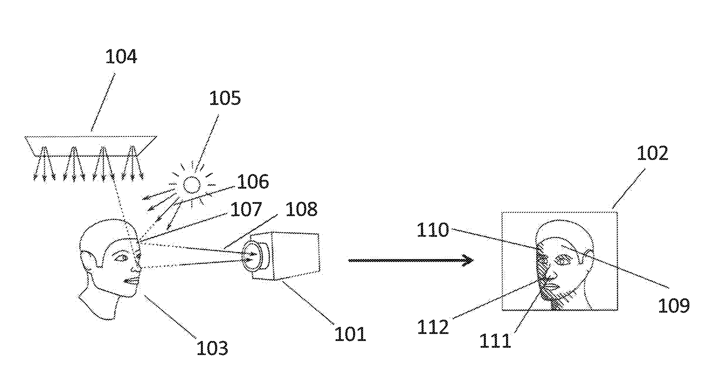
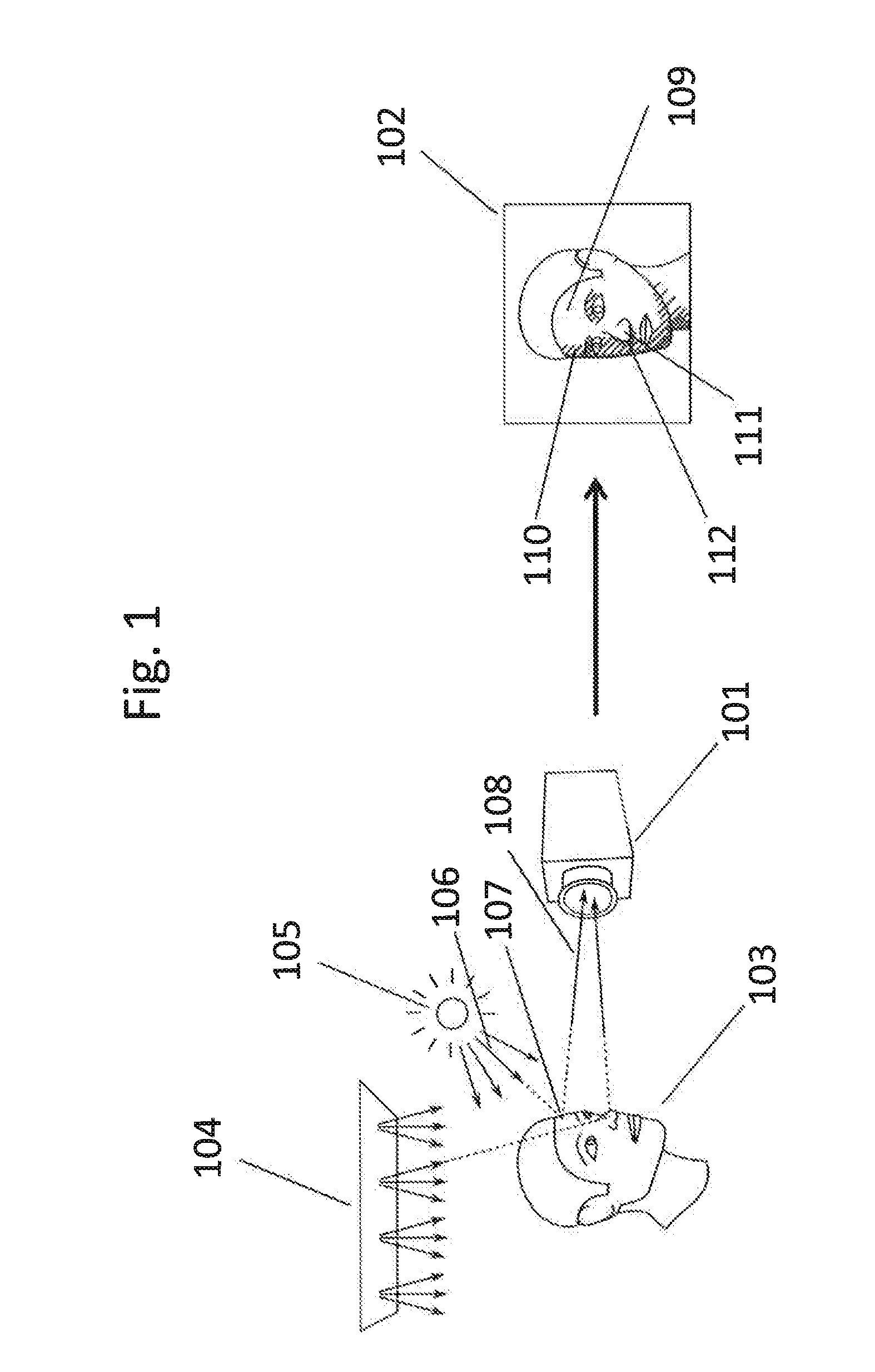
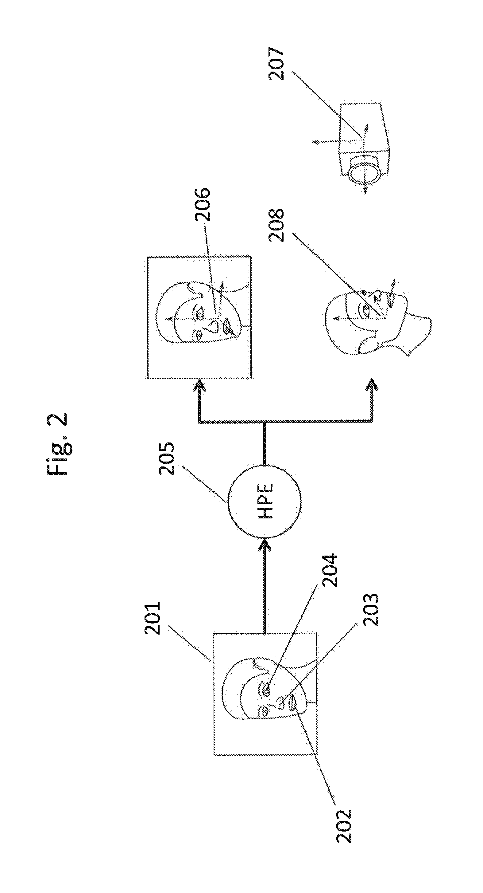
The present invention proposes to use the face of a user, who is already present in the real environment, to estimate the environment light. This has advantages as the face is available without adding extra geometry or requiring tedious setup. The face has limited variation in geometry and material, which allows for pre-processing and optimized algorithms. The face is close to the augmented view of the real environment, which supports dynamic changing illumination. The invention also uses a mathematic method to combine the determined light from two cameras. The use of the face helps consistent lighting of real and virtual content and reduces the impact of irrelevant surfaces. The distance between the user's face and the camera is typically close, making the scenario more robust for applying depth cameras. The invention also assumes a known relation between the coordinate systems of the two cameras, which allows for a desired alignment between the virtual object and the real object in the real environment. This results in augmentations with consistent illumination between real and virtual objects within the camera image.

Problems solved by technology

For augmented reality scenes, the lighting conditions are typically unknown and arbitrary, and therefore it is generally difficult or even impossible to have consistent lighting for the real and virtual objects.
This definitely restricts applicability of these approaches.
Further, most of the common approaches could only estimate directions of environment light, but not positions of any light source.
One problem of this approach is the necessity of additional setup, which, e.g., either requires a fish-eye camera lens or the mirror sphere, wherein the extra objects added to the scene change the original scene.

Method used


Image

  • Method and system for representing a virtual object in a view of a real environment
  • Method and system for representing a virtual object in a view of a real environment
  • Method and system for representing a virtual object in a view of a real environment

Examples


example

[0164]When the user is facing the mobile device (e.g., smartphone) and thereby moves or tilts the camera around, the movement of the head and the movement of the camera should be distinguished in order to integrate multiple measurements into a common “world coordinate system” and using them together to estimate the illumination.

[0165]A possible embodiment of the invention comprises a use of additional active light (photo light / flash or may be light from a screen) to artificially illuminate the face of the user in order to overcome limitations in albedo estimation. The image intensity / color does not only depend on the amount of light falling on the face, but also on the skin color / reflectance properties of the particular skin. By taking an image with added synthetic photo light and one without, the difference between the two images is the face just illuminated by the synthetic light. If we know intensity / light color of this light, we can deduct information about the surface reflectan...


PUM


Abstract

A method and system of representing a virtual object in a view of a real environment is provided which includes providing image information of a first image of at least part of a human face captured by a camera, providing at least one human face specific characteristic, determining an image area of the face in the first image as a face region, determining at least one first light falling on the face according to the face region and the at least one human face specific characteristic, and blending in the virtual object on a display device in the view of the real environment according to at least one first light. The method further includes providing a plurality of face sample positions, providing for each of the plurality of face sample positions a radiance transfer function, determining image positions of the face sample positions in the first image, and determining a first light according to intensity information associated with the image positions of the face sample positions in the first image and the radiance transfer functions associated with the face sample positions in the first image.

Description

[0001]This application is a continuation-in-part of PCT Patent Appln. No. PCT / EP2014 / 0055938 filed Mar. 25, 2014.BACKGROUND OF THE INVENTION[0002]1. Technical Field[0003]The present disclosure is related to a method and system for representing a virtual object in a view of a real environment.[0004]2. Background Information[0005]In Augmented Reality (AR), a view of a real environment, such as a video image of the real environment, is combined with an overlay of one or more virtual objects in a spatial relationship to the real environment. For many AR applications, the virtual objects shall seamlessly integrate in the view so that real and virtual objects cannot be distinguished. Therefore, it is important to illuminate or display the virtual objects with the same lighting conditions visible in the real world as well as let the virtual objects change the illumination for example by casting shadows onto parts from the real scene. For augmented reality scenes, the lighting conditions ar...

Claims


Application Information

Patent Timeline
IPC IPC(8): G06T19/00H04N13/239
CPCG06T19/006G06T2207/30201G06T2207/10004G06T15/50H04N13/239G06T7/11
Inventor KNORR, SEBASTIANMEIER, PETER
Owner APPLE INC
Learn More