
Low head room overhead door system with adjustable short radius track section

a technology of short radius and overhead door, which is applied in the direction of wing openers, multi-purpose tools, constructions, etc., can solve the problems of requiring modifications, significantly labor-intensive and counter-productive, and the inability to use the primary track radius without the auxiliary track radius in the normal head room installation

Inactive Publication Date: 2006-06-13
CLOPAY BUILDING PRODS
View PDF43 Cites 32 Cited by
  • Summary
  • Abstract
  • Description
  • Claims
  • Application Information

AI Technical Summary

Benefits of technology

"The present invention is an improvement for overhead door systems used in low head room environments. It solves issues with previous systems by using adjustable short radius track members that can be adjusted to accommodate different door openings and environments. The short radius members have V-shaped notches that allow for easy adjustment, and a detent to stop the guide roller. The invention also includes a spacer for long horizontal angle rails and a groove in the moveable sheave for use with extension spring systems. These features make the overhead garage door system easier to install and use, and maximize vertical clearance while still aligning the lift cable with the door tracks."

Problems solved by technology

Overtime, such springs may fail and the tension and energy stored in those springs is rapidly released which causes the overhead door system to malfunction.
Due to the size and weight of the overhead garage door components, and the general complexity associated with their assembly, overhead garage door systems typically are shipped by the manufacturer to a dealer for assembly at a site by a professional installer.
With this known approach, however, the primary and auxiliary track radiuses are not separable from the corner bracket, so the primary track radius cannot be used without the auxiliary track radius in normal head room installations.
Such modifications are required and significantly labor intensive and counter productive to an efficient and quality overhead door installation process.

Method used


Image

  • Low head room overhead door system with adjustable short radius track section
  • Low head room overhead door system with adjustable short radius track section
  • Low head room overhead door system with adjustable short radius track section

Examples


Embodiment Construction

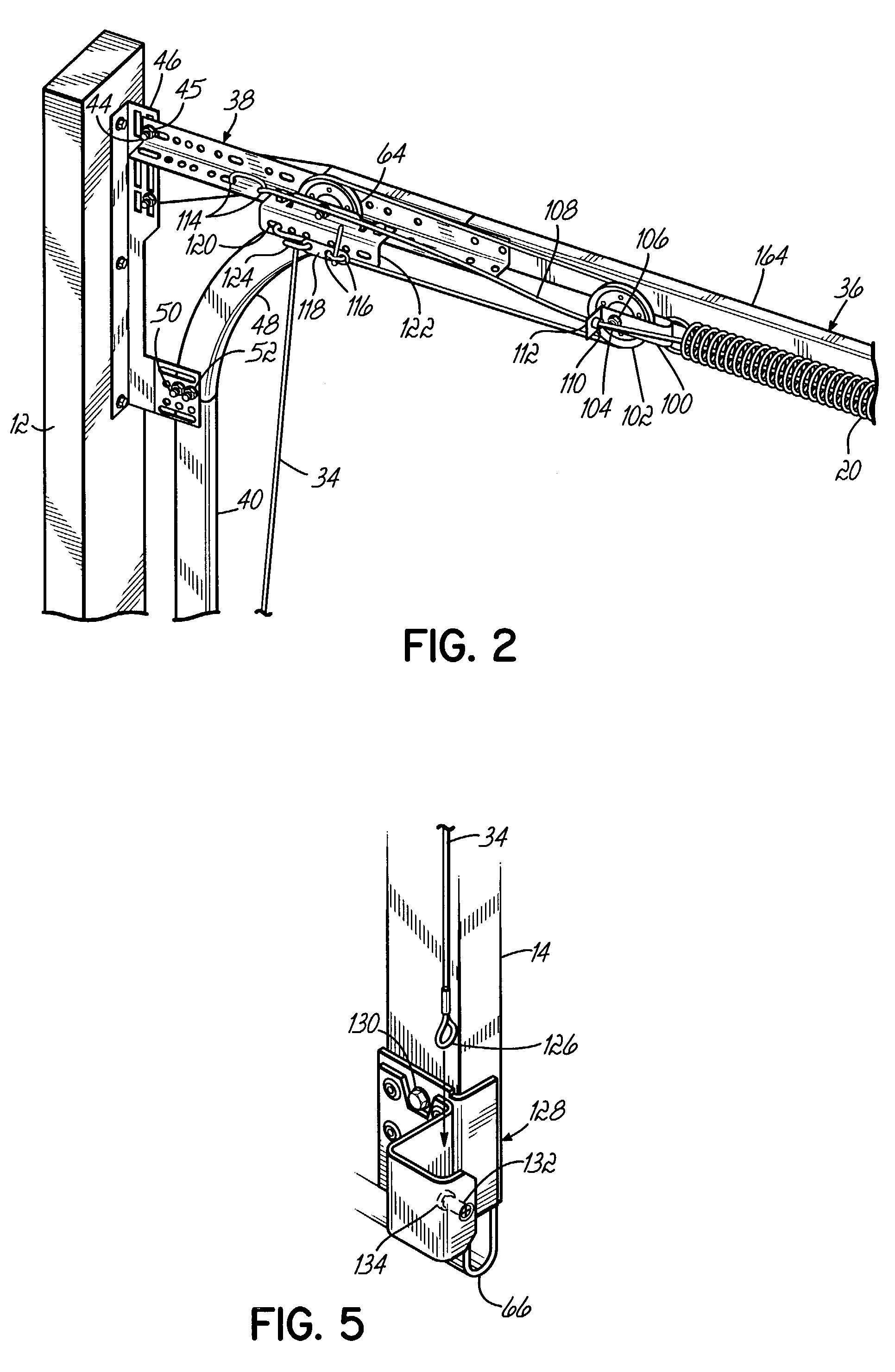
[0034]With reference to the Figures, and to FIG. 1 in particular, a low head room overhead door system 10 is shown in accordance with the principles of the present invention. The low head room overhead door system 10 includes a conventional door frame 12 that defines an opening into a garage, and a series of interconnected door panels 14 that articulate between a vertical position as shown if FIG. 1 and an overhead, horizontal position not shown. Door tracks 16 (one shown) are located on either side of the door panels for guiding movement of the door panels between the horizontal and vertical positions. While only one door track 16 is shown in FIG. 1, it will be appreciated that the other door track located on the opposite side of door panels mirrors the track 16 shown and is otherwise identical in construction.

[0035]The present invention may utilize either a torsion spring 18, as shown in FIG. 1, or a plurality of extension springs 20, one of which is shown in FIG. 2, to counterbal...


PUM


Abstract

A universal overhead door system includes a pair of horizontal track members, a pair of vertical track members and a pair of track radius members interconnecting the horizontal and vertical track members. A pair of adjustable short radius members extend from the track radius members to guide uppermost rollers of an overhead sectional door. The overhead door system includes a pair of stationary sheaves positioned outboard of a pair of horizontal support rails which support the horizontal track members. A detent is provided at one end of the adjustable radius members to prevent undesirable travel the garage door. A spacer is provided for use in extension spring configurations when a long horizontal support rail is required. The spacer prevents metal-to-metal contact of moveable sheaves with the horizontal support rails.

Description

[0001]The present application claims the benefit of U.S. Provisional Application Ser. No. 60 / 375,348, filed Apr. 25, 2002, the disclosure of which is hereby incorporated by reference in its entirety.FIELD OF THE INVENTION[0002]The present invention relates generally to overhead door systems and, more particularly, to an overhead door system for use in low head room environments.BACKGROUND OF THE INVENTION[0003]Overhead garage door systems are widely used in both residential and commercial applications, and are designed to be operated either manually or automatically through a reversible motor. Overhead garage doors include a series of interconnected door panels that are connected along their longitudinal edges by one or more hinges to provide pivotal movement of the door panels between vertical and horizontal positions as is known in the art. The door panels include a series of roller brackets mounted on opposite sides of the door panels for supporting a series of rollers. The rolle...

Claims


Application Information

Patent Timeline
Patent Type & Authority Patents(United States)
IPC IPC(8): E05F15/00E05D15/24E05F15/16
CPCE05D15/24E05D15/246E05D13/1261E05F15/686E05Y2900/106Y10T16/84E05Y2201/684
Inventor LEWIS, JR., RICHARD J.STONE, JEFFREY W.YOUTSEY, THOMAS E.
Owner CLOPAY BUILDING PRODS
Learn More