Wing in ground effect vehicle with endplates

a technology of endplates and wigs, which is applied in the field of wigs with endplates, can solve the problems of incurring severe wave impact pressure at cruise speed, the prior art has not taken advantage, and the inability to design wave piercing endplates

Inactive Publication Date: 2006-06-13
COSMOS HLDG LTD
View PDF21 Cites 17 Cited by
  • Summary
  • Abstract
  • Description
  • Claims
  • Application Information

AI Technical Summary

Benefits of technology

[0024]It is an object of the invention to provide an improved wing in ...

Problems solved by technology

This is because of the extremely high wave impact forces that would be incurred at cruise speed.
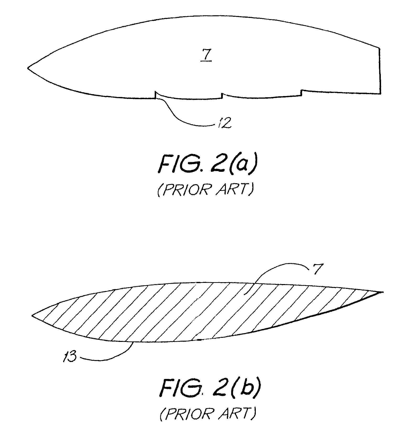
The existing prior art has not taken advantage of the above as it has been assumed to be impossible to design wave piercing endplates that would (i) have a low enough drag in the water and (ii) be stable at expected angles of yaw at design cruise speed.
Because these designs are still relatively thick they would incur severe wave impact pressures at cruise speed as well as high drag.
This restricts their ability to reduce the induced drag.
Typical lift/drag ratios of Russian craft are around 18:1 and the ARPA Report study was unable to significantly improve on this figure even for a very large craft of 5,000 tonnes (after making changes required to achieve the longer range set by the study).
As these lift/drag ratios are no better than those achieved by aircraft it is understandable why WIGs have never been commercialised.
These endplates were designed to...

Method used


Image

  • Wing in ground effect vehicle with endplates
  • Wing in ground effect vehicle with endplates
  • Wing in ground effect vehicle with endplates

Examples


Embodiment Construction

[0137]FIGS. 6(a) through 6(c) depict a wing in ground effect vehicle according to a preferred embodiment of the present invention. The wing in ground effect vehicle is provided with a fuselage 2 and wing structure 3 with opposing wing tip portions. A pair of endplates 17, each having a proximal root 33, bottom or distal tip 19, leading edge 20 and trailing edge 22, extend downwardly from endplate bulkheads 34 at the wingtip portions to below the fuselage 2 and wing structure 3. This enables the endplates 17 to be immersed in water 26 during flight thereover as depicted in FIG. 6(b) whilst keeping the fuselage 2 and wing structure 3 airborne. In flight, the endplates will typically be slightly submerged below the surface 9 of the water 26 even in the trough 18 of waves 21, depicted in phantom in FIG. 6(b). As there is no air gap between the distal tip 19 of the endplates 17 and the water 26 the induced drag of the WIG is reduced, thereby increasing the lift / drag ratio of the WIG. To ...


PUM


Abstract

A Wing In Ground Effect Vehicle has a pair of supercavitating endplates (17) which extend below the fuselage (2) such that they can be immersed in water during flight thereover. The endplates have a nose (28) defining a leading edge (20) and adapted to generate a supercavity. The endplates (17) typically pivot about a pivot axis P to provide a stabilising weathercock-type effect.

Description

[0001]This application is a continuation-in-part of application Ser. No. 09 / 573,385, filed May 18, 2000 now abandoned.FIELD OF THE INVENTION[0002]The present invention relates to Wing In Ground Effect Vehicles (WIGs) and more particularly to WIGs with endplates that operate over water.BACKGROUND OF THE INVENTION[0003]A significant part of the drag of transport aircraft is made up of induced drag. Flying in ground effect close to the ground or water can reduce this drag. Numerous WIGs have been developed and flown.[0004]Several large WIG designs have been proposed but never built. These are summarised in two reports, “Air Cushion Craft Development (First Revision)” (DTNSRDC Report 80 / 012 (4727 revised) January 1980) by Peter J. Mantle (hereinafter referred to as the Mantle Report), and “Wingship Investigation” (Advanced Research Projects Agency, Sept. 30, 1994) (hereinafter referred to as the ARPA Report).[0005]Because the height of land varies so much it is normal to fly WIGs over w...

Claims


Application Information

Patent Timeline
IPC IPC(8): B63B1/34B60V3/08B60V1/08B60V1/22
CPCB60V1/22B60V1/08Y02T50/10B60V1/18
Inventor ALLEN, KEN R.
Owner COSMOS HLDG LTD
Why Eureka
Try Eureka