Eureka AIR delivers breakthrough ideas for toughest innovation challenges, trusted by R&D personnel around the world.

Disk drive servo controller utilizing an extended servo header

a servo controller and disk drive technology, applied in the field of disk drives, can solve the problems of disk drive dropping or being subjected, eccentricity associated with the rotating disk, and eccentricity of the read servo wedg

Inactive Publication Date: 2006-06-06
WESTERN DIGITAL TECH INC
View PDF19 Cites 146 Cited by
  • Summary
  • Abstract
  • Description
  • Claims
  • Application Information

AI Technical Summary

Benefits of technology

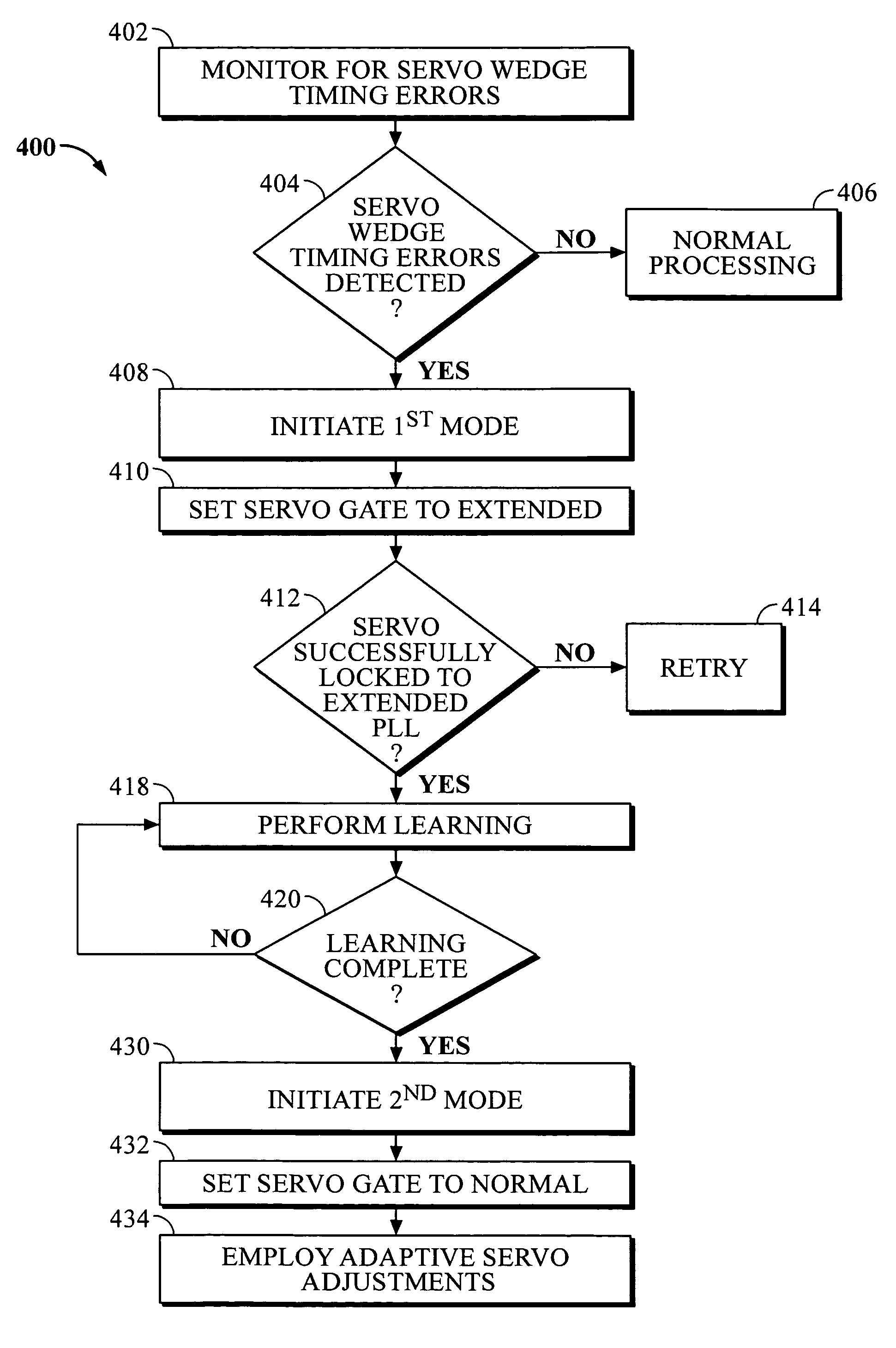
[0020]The method to compensate for servo wedge timing errors due to eccentricity associated with the servo wedges of a circumferential track includes locking to an extended servo header and performing servo wedge timing error learning to characterize s...

Problems solved by technology

Eccentricity associated with a rotating disk drive, which results in associated eccentricity of read servo wedges upon which the servo control system operates, may occur for a number of reasons.
When a disk is servo-written by a media writer and mounted in the HDA, it may not be properly aligned resulting in eccentricity associated with the rotating disk.
Additionally, the disk drive may be dropped or be subjected to some sort of operational shock, which further adds to eccentricity problems.
For all of these reasons, the disk may not be at the center of rotation resulting in the disk and the servo wedges turning with eccentricity.
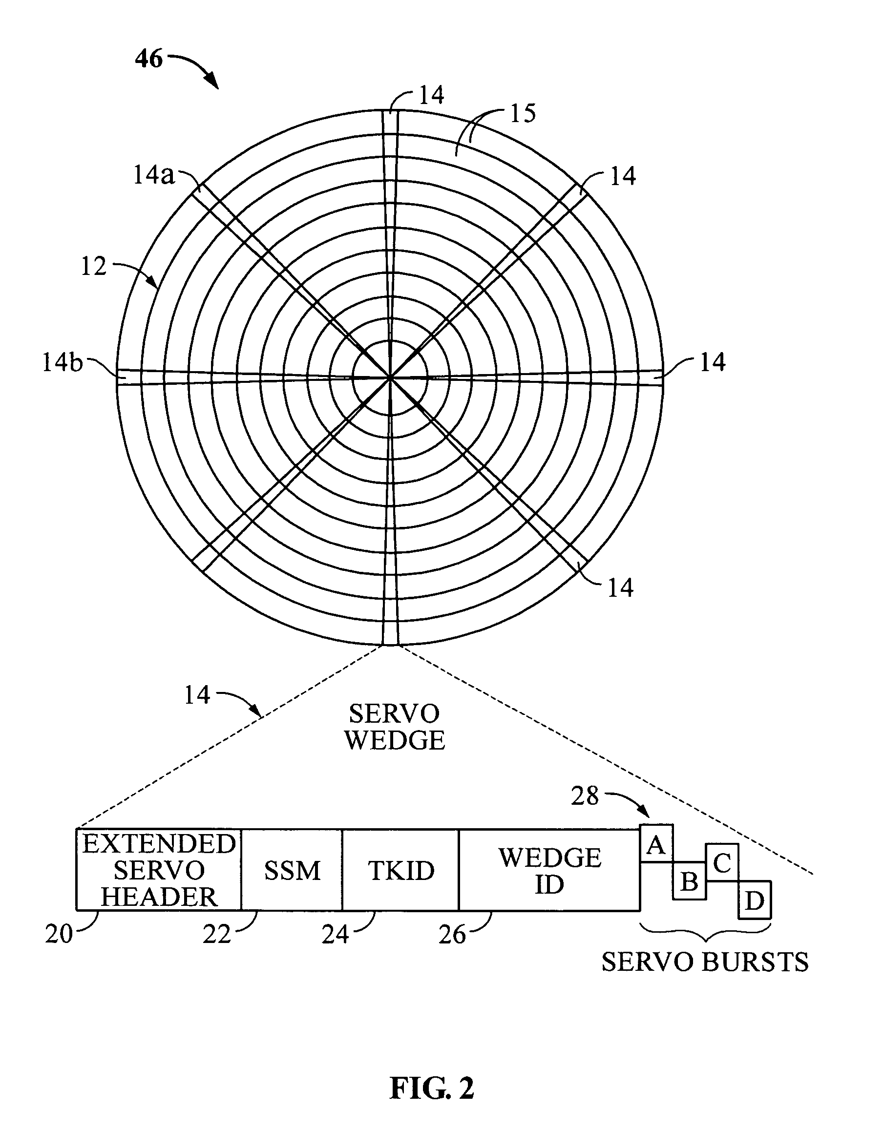
When this occurs, the servo wedges appear to the servo control system as if they are not evenly spaced such that timing uncertainties are introduced thereby causing problems in both the reading and writing of data.
Accordingly, the eccentricity associated with the servo wedges results in timing uncertainties being introduced into the servo control system such that resultant servo control signals to control the writing of data also include these timing errors.
Unfortunately, present-day servo control systems before implementing DSW, when confronted with eccentricity problems, may often take a long time and be very inefficient in locking onto the servo header and implementing DSW, or may never lock onto the servo header resulting in the failure of the disk drive.

Method used


Image

  • Disk drive servo controller utilizing an extended servo header
  • Disk drive servo controller utilizing an extended servo header
  • Disk drive servo controller utilizing an extended servo header

Examples


Embodiment Construction

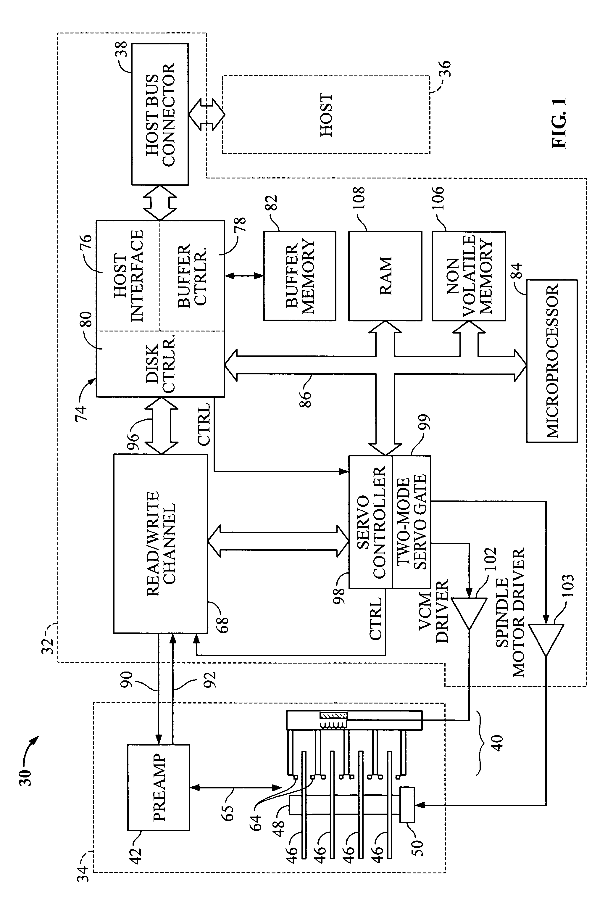
[0028]FIG. 1 shows a block diagram of disk drive 30, in which embodiments of the invention may be practiced. One suitable standard for such connection is the Advance Technology Attachment (ATA) standard presently favored for desktop personal computers. Disk drive 30 comprises a Head / Disk Assembly, HDA 34, and a controller printed circuit board assembly, PCBA 32.

[0029]The HDA 34 comprises: one or more disks 46 for data storage; a spindle motor 50 for rapidly spinning each disk 46 (four shown) on a spindle 48; and an actuator assembly 40 for moving a plurality of heads 64 in unison over each disk 46. The heads 64 are connected to a preamplifier 42 via a cable assembly 65 for reading and writing data on disks 46. Preamplifier 42 is connected to channel circuitry in controller PCBA 32 via read data line 92 and write data line 90.

[0030]Controller PCBA 32 comprises a read / write channel 68, servo controller 98, host interface and disk controller HIDC 74, voice coil motor driver VCM 102, sp...


PUM


Abstract

A disk drive includes a moveable head and a disk having a circumferential track which includes a plurality of servo wedges. The servo wedges are spaced sequentially around a circumference of the circumferential track. Each servo wedge includes an extended servo header. The disk drive includes a servo controller to perform track following with the moveable head. The servo controller compensates for servo wedge timing errors due to eccentricity associated with the servo wedges of the circumferential track by implementing: a first mode in which the servo controller locks to the extended servo header of a servo wedge and performs servo wedge timing error learning to characterize servo wedge timing errors and a second mode to adapt servo control signals of the servo controller based on the characterized servo wedge timing errors of the first mode in order to dynamically compensate for the eccentricity associated with the servo wedges.

Description

BACKGROUND OF THE INVENTION[0001]1. Field of the Invention[0002]The present invention relates to disk drives. More particularly, the present invention relates to a disk drive servo controller that utilizes an extended servo header.[0003]2. Description of the Prior Art and Related Information[0004]Computer systems often rely on disk drives for storing and retrieving data. Disk drives typically employ a moveable head actuator to frequently access large amounts of data stored on a disk. One example of a disk drive is a hard disk drive. A conventional hard disk drive has a head disk assembly (“HDA”) including at least one magnetic disk (“disk”), a spindle motor for rapidly rotating the disk, and a head stack assembly (“HSA”) that includes a head gimbal assembly (HGA) with a moveable transducer head for reading and writing data. The HSA forms part of a servo control system that positions the moveable transducer head over a particular track on the disk to read or write information from an...

Claims


Application Information

Patent Timeline
IPC IPC(8): G11B5/09
CPCG11B5/59627
Inventor KUPFERMAN, HANAN
Owner WESTERN DIGITAL TECH INC
Why Eureka
Eureka Blog
Learn More