
Reflected backdrop for communications systems

a technology of communication system and backdrop, applied in the field of video conferencing apparatus, can solve the problems of inability to address prior art, degrade the image of the person, and color shift, and achieve the effect of increasing the siz

Active Publication Date: 2006-06-06
TELEPRESENCE TECH
View PDF49 Cites 43 Cited by
  • Summary
  • Abstract
  • Description
  • Claims
  • Application Information

AI Technical Summary

Benefits of technology

The system achieves a compact and practical design that fits in most spaces, maintains image quality by avoiding ghost effects, and ensures eye contact, making it suitable for various applications including retail, banking, and teaching, while providing a scalable solution for larger groups.

Problems solved by technology

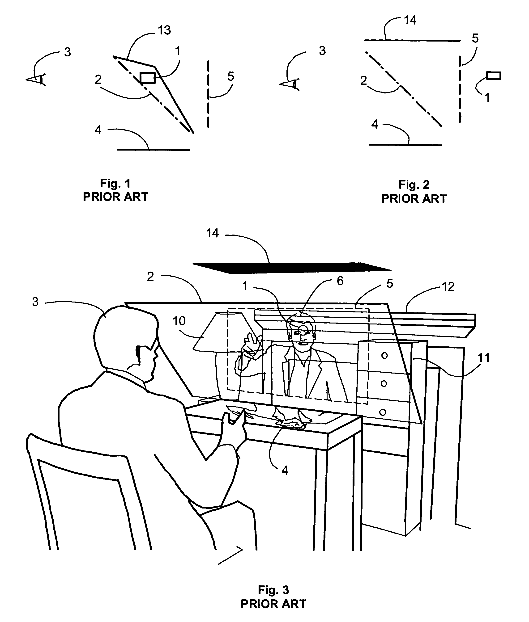
A disadvantage of this configuration is that a color shift can take place when the reflection on the two-way mirror 2 is viewed from an angle of approximately 45 degrees.
Also, any imperfections or distortion in the two-way mirror will cause the image of the person to be degraded.
This can be a particular problem if the two-way mirror is comprised of plastic or Mylar substrate.
This prior art does not address the problems that may arise from the superimposing of the reflected image of the setting with the camera 1.
While this would provide a clear view of the image on the image display device, it would only display a flat view that would not achieve the desired sense of presence with depth relationships.

Method used


Image

  • Reflected backdrop for communications systems
  • Reflected backdrop for communications systems
  • Reflected backdrop for communications systems

Examples


Embodiment Construction

[0086]Referring now to the drawings, wherein like reference numbers are used to designate like elements throughout the various views, several embodiments of the present invention are further described. The figures are not necessarily drawn to scale, and in some instances the drawings have been exaggerated or simplified for illustrative purposes only. One of ordinary skill in the art will appreciate the many possible applications and variations of the present invention based on the following examples of possible embodiments of the present invention.

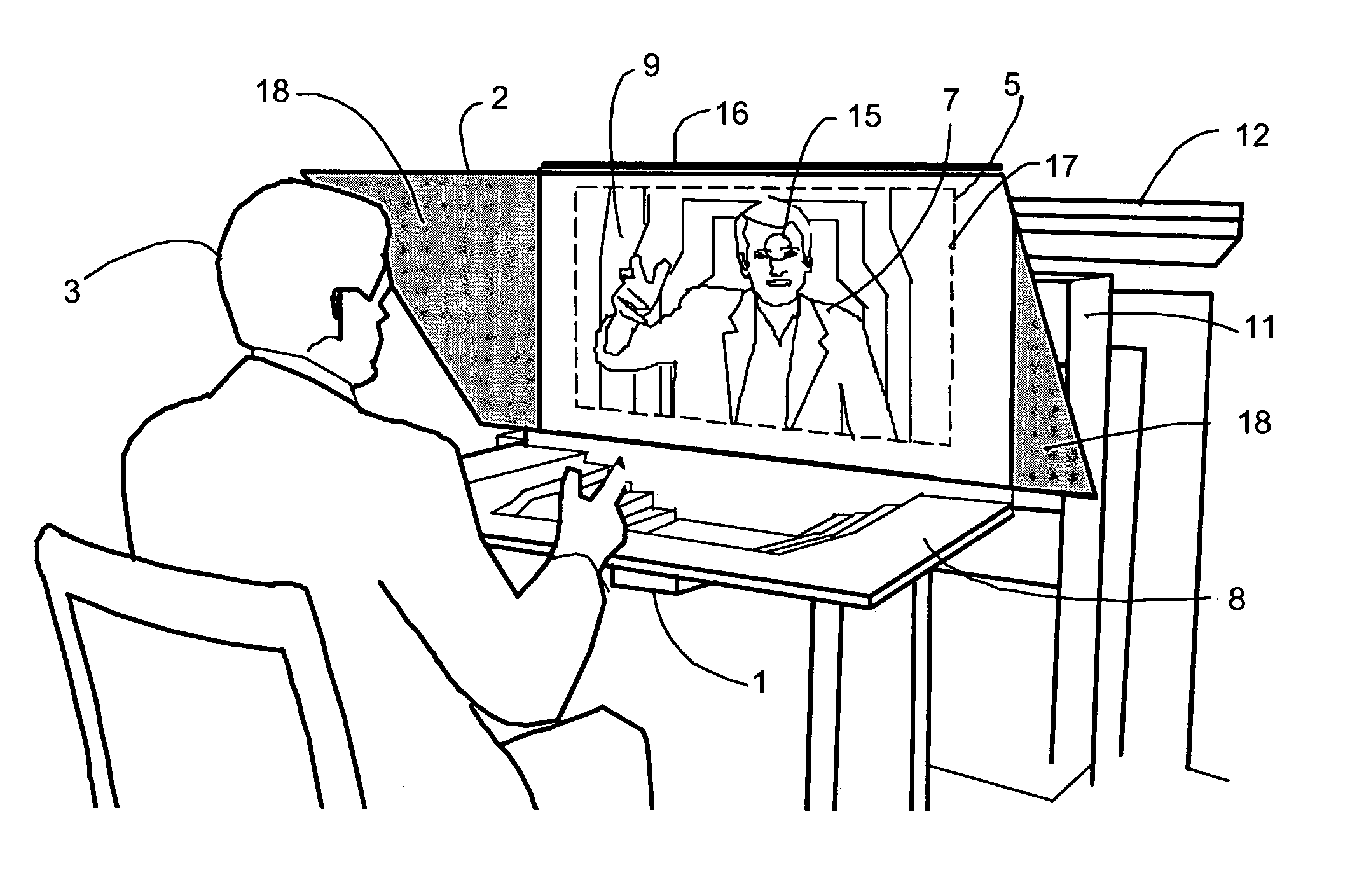
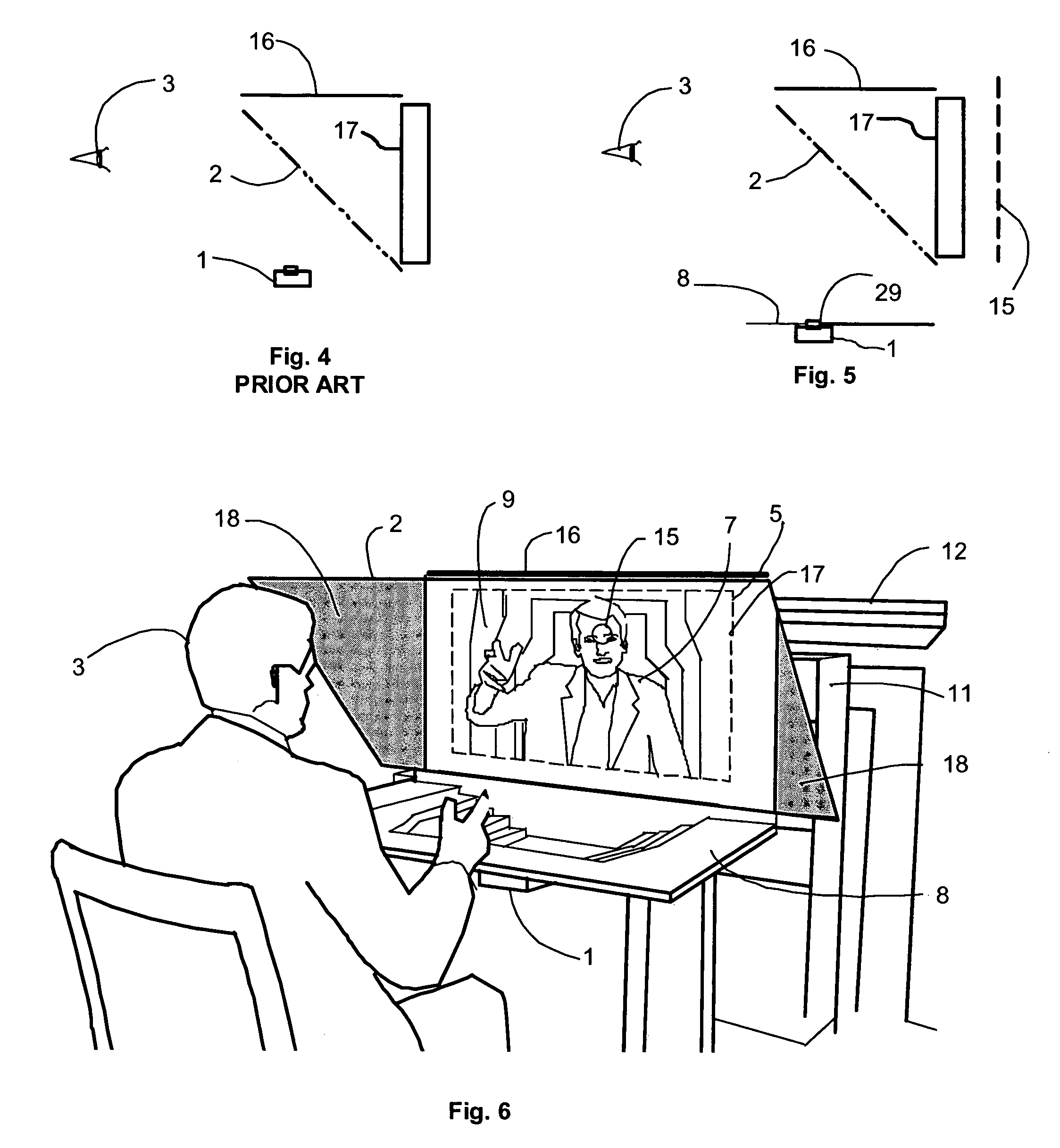
[0087]FIG. 5 shows an embodiment of the present invention with a displayed image 17 located at a first plane which is viewed by an observer 3 through a two-way mirror 2. A light colored or illuminated backdrop 8 is a distance from the two-way mirror 2 that is viewed as a reflection 15 by the observer 3 at a second plane. The backdrop 8 is positioned further away from the two-way mirror 2 than the image on the image display device 17 so tha...


PUM


Abstract

A video conferencing system has a two-way mirror, which is between the observer and the display device, positioned at an angle to reflect a backdrop surface. The backdrop surface, which is further away from the two-way mirror than the image plane of the image display device, appears superimposed in a position behind the image of a person from the remote location. A camera is located in the backdrop at a position along the line of sight of the transmitted image so that a perceived eye contact is achieved.

Description

[0001]This application claims priority to provisional patent application Ser. No. 60 / 564,098, filed Apr. 21, 2004, and entitled “Reflected Background for Communications System,” which application is hereby incorporated herein by reference.TECHNICAL FIELD[0002]The present invention relates to video conferencing apparatus and more particularly to apparatus that displays the transmitted participant to appear to be in front of a backdrop and to have a perceived eye contact.BACKGROUND[0003]There is a need for a new type of distance communications system that achieves “telepresence” which is commonly understood to be a perception of presence of a person from a distant location. Telepresence covers a broad range of display and interactive technologies. Most configurations display a flat image on a screen or a monitor. The flat images produced by these products and display systems do not create the perception of the presence of the transmitted person in the three dimensional setting of the ...

Claims


Application Information

Patent Timeline
Patent Type & Authority Patents(United States)
IPC IPC(8): H04N7/14G03B15/00G03B21/00
CPCH04N7/144G03B15/10
Inventor WHITE
Owner TELEPRESENCE TECH
Learn More