
Notebook computer force-controlled pointing stick device

a technology for notebook computers and pointing sticks, which is applied in the direction of portable computer details, electric apparatus casings/cabinets/drawers, instruments, etc., can solve the problems of increased friction/texture, inconvenient or difficult connection, and increased use of firm caps for users, so as to improve typing efficiency, improve control, and enhance ergonomic features

Inactive Publication Date: 2006-06-06
LENOVO (SINGAPORE) PTE LTD
View PDF16 Cites 9 Cited by
  • Summary
  • Abstract
  • Description
  • Claims
  • Application Information

AI Technical Summary

Benefits of technology

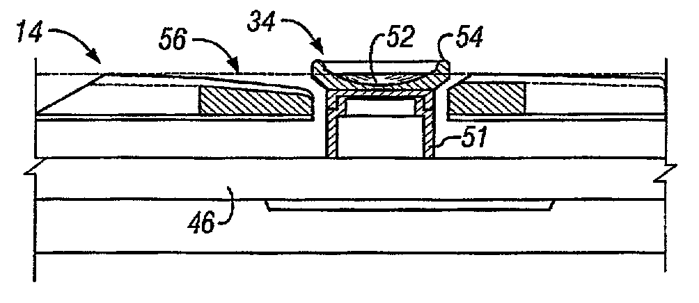
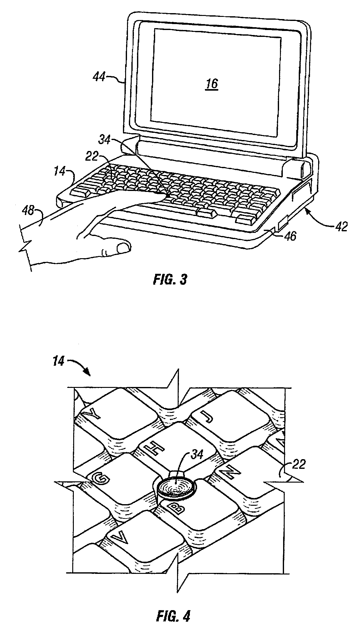
[0011]One embodiment of a notebook computer force-controlled pointing stick device incorporates a more comfortable cap with enhanced ergonomic features. The device is generally cylindrical in shape and is located between the G, H, and B keys on the computer keyboard. The upper end of the device has a donut-like shape with a concave or crown-shaped central portion that forms well to the user's finger and provides better control, but does not interfere with typing. The upper end preferably has a rubber tip that provides improved control for a finger of the user. In an alternate embodiment, the device is similar in shape to a bicycle saddle.

Problems solved by technology

A keyboard with such an integrated pointing device is especially desirable in a portable computer, having a graphical user interface, where it can be inconvenient or difficult to connect and / or use a mouse or track ball with the computer to control display pointer movement.
In addition, the firm cap can be uncomfortable for some users as it deforms the user's finger, and its rough surface abrades the skin with can callus the fingertip.
When these elements are combined with the convex shape of the current design, which does not provide the user with significant surface area for finger contact, the need to rely more friction / texture is increased.
Moreover, novice users may consider the design to be unintuitive because the shape implies that it is a joystick, and thus expect the actuator to move more freely in the x-and-y-axes.

Method used


Image

  • Notebook computer force-controlled pointing stick device
  • Notebook computer force-controlled pointing stick device
  • Notebook computer force-controlled pointing stick device

Examples


Embodiment Construction

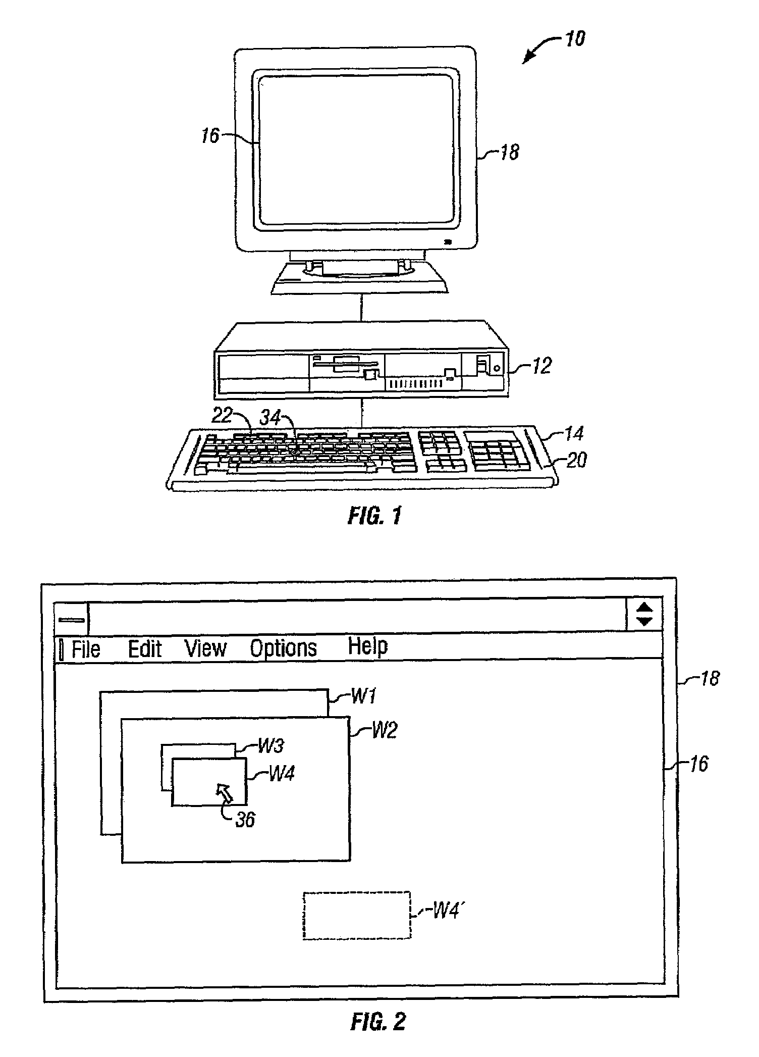
[0022]Referring to FIG. 1, a computer system 10 comprises a system unit 12 that receives manual control inputs from an attached keyboard unit 14. System unit 12 displays system responses on a display screen 16 of a display device 18. The keyboard unit 14 includes a surrounding frame 20 that supports a plurality of manually depressible keys 22. The keys 22 include the normal twenty-six keys bearing the letters of the alphabet which are arranged in the conventional QWERTY layout. The keys 22 also include conventional F1 through F12 function keys, and other keys such as caps lock, shift, tab, backspace, enter, and so forth. The keyboard unit 14 further includes a space bar key, control keys, alternate keys, etc.

[0023]The keyboard unit 14 has a small, substantially rigid pointing device or actuator 34 embedded therein between the G, H, and B keys. The actuator 34 can be engaged by the tip of one of the user's fingers. In addition, lateral forces may be applied simultaneously over a 360 ...


PUM


Abstract

A notebook computer force-controlled pointing stick device incorporates a more comfortable cap with enhanced ergonomic features. The device is generally cylindrical in shape and is located between the G, H, and B keys on the computer keyboard. The upper end of the device has a donut-like shape with a concave or crown-shaped central portion that forms well to the user's finger and provides better control, but does not interfere with typing. The upper end preferably has a rubber tip that provides improved control for a finger of a user. In an alternate version, the device is similar in shape to a bicycle saddle.

Description

BACKGROUND OF INVENTION[0001]1. Technical Field[0002]The present invention relates in general to an improved pointing stick device for a notebook computer, and in particular to an ergonomically enhanced notebook computer force-controlled pointing stick device.[0003]2. Description of the Prior Art[0004]The interactive computer system operating environment, such as that encountered by users of personal computers and the like, is characterized by efforts toward increasing ease of operation and improved ergonomics. An important contribution to making the operation of such computers easier and more convenient is the graphical user interface (GUI). A GUI provides a computer interface that is visually oriented and includes a variety of graphical artifacts displayed on a computer display that make the operation of the computer more intuitive, thereby increasing user efficiency.[0005]A GUI operating system enables a user to move a computer display pointer by using a GUI pointing device, such...

Claims


Application Information

Patent Timeline
IPC IPC(8): G09G5/08G06F1/16G06F3/033
CPCG06F1/1616G06F3/0338G06F1/169G06F1/1632
Inventor HILL, DAVID WAYNEMIEKI, NARAIKISAWIN, DAVID ANDREWSHIMA, HISASHISTEWART, AARON MICHAELTAKAHASHI, TOMOYUKIYAMAZAKI, KAZUHIKO
Owner LENOVO (SINGAPORE) PTE LTD
Learn More