Power system management method and power system management system

a technology of power system and management method, applied in non-electric variable control, process and machine control, instruments, etc., can solve problems such as significant problems or accidents in the system operation

Inactive Publication Date: 2006-05-30
MITSUBISHI ELECTRIC CORP
View PDF26 Cites 4 Cited by
  • Summary
  • Abstract
  • Description
  • Claims
  • Application Information

AI Technical Summary

Benefits of technology

[0045]As a result of such arrangement, there are following advantages. The internal information regarding the mentioned equipment control apparatus can be obtained and the state of the mentioned power system can be monitored with this internal information from outside of the mentioned equipment control apparatus. Further, the function of the mentioned equipment control apparatus may be changed from at least one of the mentioned product supply-side base and power supply-side base. Furthermore, the common memory is operated only for reading with respect to the access via the mentioned Web communication net, whereby the mentioned common memory cannot be rewritten in such a manner as to change the function of the mentioned equipment control apparatus. Therefore, it can be securely prevented without fail that any other person not in charge of changing the function of the mentioned equipment control apparatus may unwillingly change the function of the mentioned equipment control apparatus.

Problems solved by technology

As a result, there is a possibility that any other persons not in charge of the maintenance monitoring and the relay setting change may unwillingly change the relay setting due to simple key manipulation mistake and the like.
Moreover, it is possible that any information regarding the power system state be changed, which may lead to a significant problem or accident in terms of system operation.

Method used


Image

  • Power system management method and power system management system
  • Power system management method and power system management system
  • Power system management method and power system management system

Examples


embodiment 1

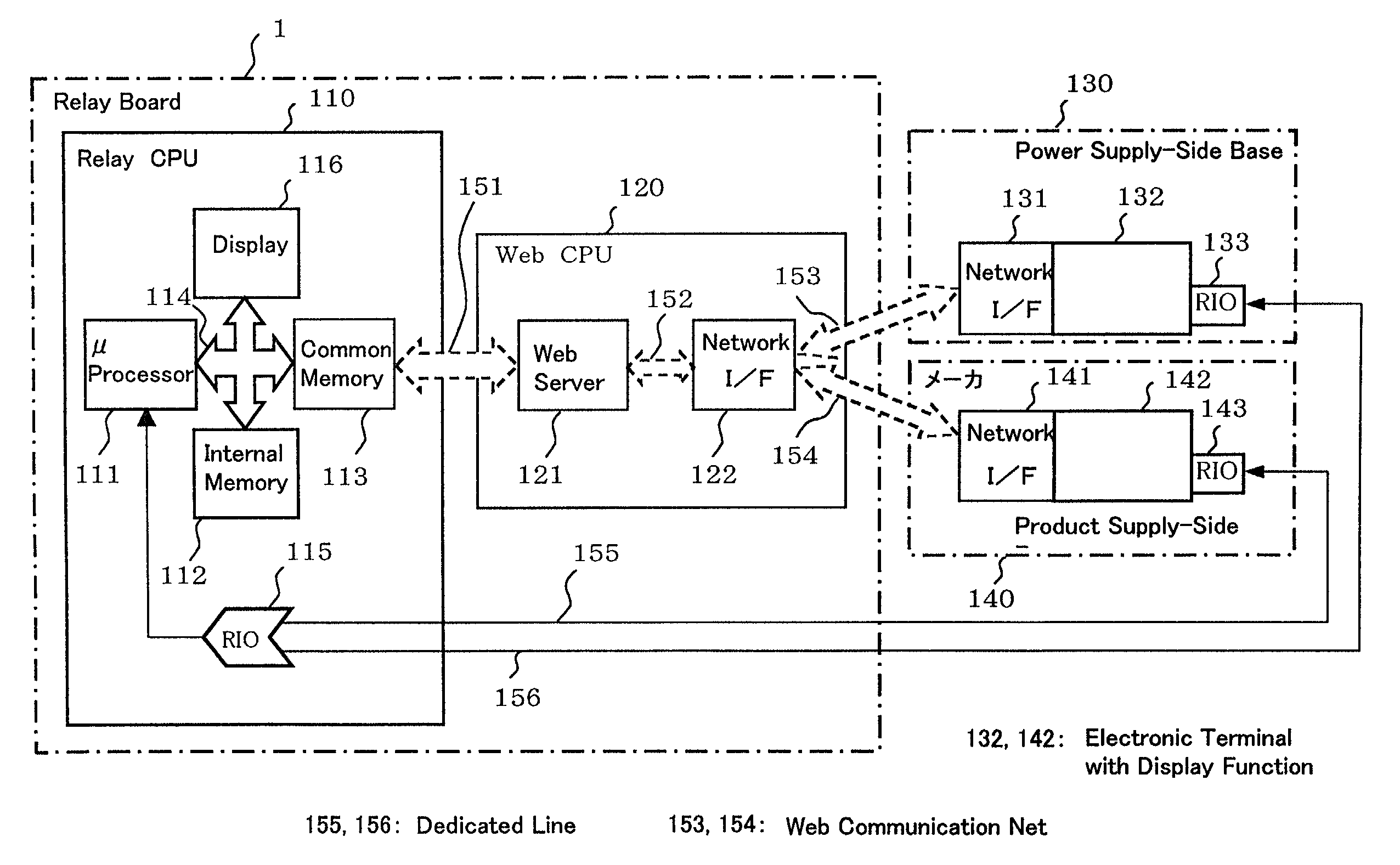
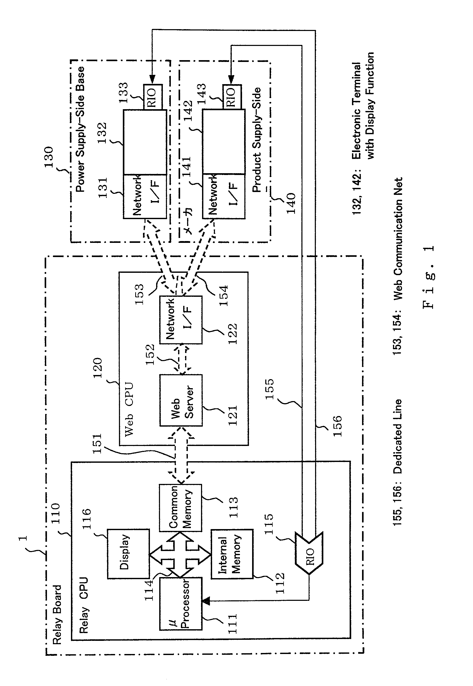
[0056]A first embodiment is hereinafter described with reference to FIG. 1. In the drawing, reference numeral 1 designates an equipment control apparatus such as a relay board (hereinafter for convenience sake referred to as “relay board”). Numeral 110 designates a relay CPU, which is comprised of a μ processor 111, an internal memory 112, a common memory 113, a data bus 114 and a RIO (a remote input output apparatus) 115. Further, the mentioned internal memory 112 and the mentioned common memory 113 are respectively comprised of separate individual chips. Numeral 120 designates a Web CPU, which is provided independently of the mentioned relay CPU 110 to serve as a CPU dedicated to a Web communication in a WWW, and comprised of a Web server 121 and a network I / F 122.

[0057]Numeral 130 designates a power supply-side base, which is comprised of a network I / F 131, an electronic terminal 132 such as personal computer and a RIO (remote input output apparatus) 133. The power supply-side ba...

embodiment 2

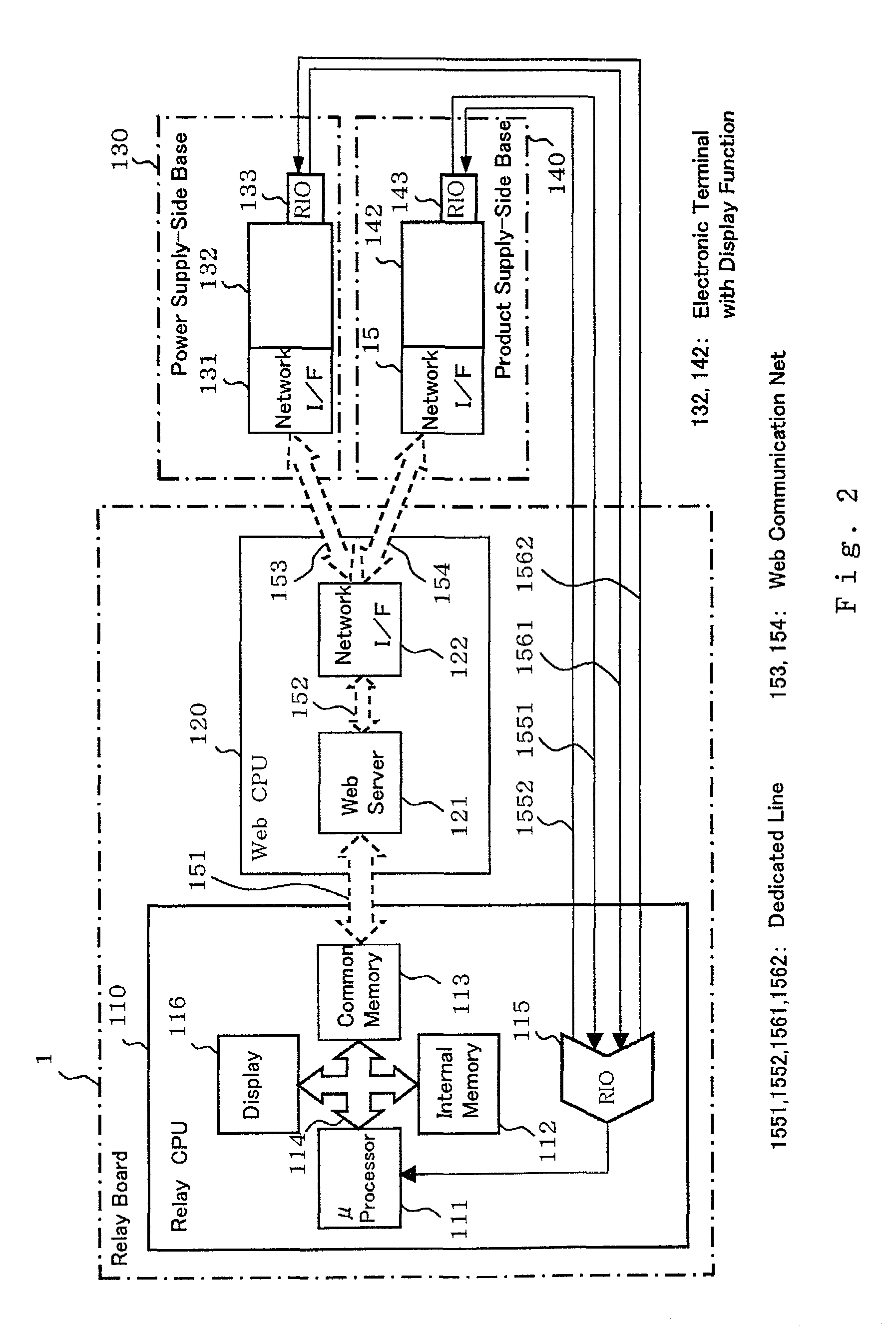
[0086]Now, a second embodiment is hereinafter described with reference to FIG. 2. In the drawing, reference numerals 1551, 1552 designate dedicated lines between the RIO 143 in the mentioned product supply-side base 140 and the RIO 115 in the mentioned relay CPU 110. Reference numerals 1561, 1562 designate dedicated lines between the RIO 133 in mentioned power supply-side base 130 and the RIO 115 in the mentioned relay CPU 110.

[0087]In the case that a request for access has been made from the mentioned product supply-side base 140 to the mentioned relay CPU 110 via the mentioned dedicated line 1551, whether or not such a request for access has been made from the mentioned product supply-side base 140 is confirmed by the mentioned relay CPU 110 side via the mentioned dedicated line 1552. Only after having confirmed that the access request was made from the mentioned product supply-side base 140, the access is permitted to the mentioned product supply-side base 140 via the mentioned d...

embodiment 3

[0091]Now, a third preferred embodiment is hereinafter described with reference to FIG. 3. In the drawing, reference numeral 157 designates a dedicated signal line channel, and a switch 158 which is artificially ON / OFF controlled is inserted therein. Only in the case of this switch 158 being ON, the mentioned dedicated line 155 is operative, and the RIO 115 on the side of mentioned relay board 1 operates such that transfer of information may be carried out between the electronic terminal 142 in the mentioned product supply-side base 140 and the μ processor 111 in the mentioned relay CPU 110. In the same manner, only in the case of the mentioned switch 158 being ON, the mentioned dedicated line 156 is operative, and the RIO 115 on the side of mentioned relay board 1 operates such that transfer of information may be carried out between the electronic terminal 132 of the mentioned power supply-side base 130 and the mentioned μ processor 111.

[0092]Further, the mentioned switch 158 is co...


PUM


Abstract

Function of an equipment control apparatus is changed from outside of the equipment control apparatus by means of a communication method of higher security than that of a monitoring system operating via a Web communication net: the equipment control apparatus being provided on the side of facility equipments constituting a power system and controlling the facility equipments; and the monitoring control apparatus being provided outside of the equipment control apparatus and obtaining internal information about the equipment control apparatus via the Web communication net to monitor a state of the power system from the internal information.

Description

BACKGROUND OF THE INVENTION[0001]1. Technical Field[0002]The present invention relates to a power system management method and to a power system management system for changing a function of equipment control apparatus, in a power system comprising an equipment control apparatus provided on the side of facility equipments constituting the power system and controlling the mentioned facility equipments, and a monitoring control apparatus provided outside of the mentioned equipment control apparatus and receiving internal information about the mentioned equipment control apparatus via a web communication net thereby monitoring states of the mentioned power system on the basis of the mentioned internal information.[0003]2. Background Art[0004]Hitherto, management of a power system has been carried out in the following manner. For example, any maintenance man who opens a relay board and inspecting it conducts maintenance of the relay board. Also, a relay board manufacturer directly settin...

Claims


Application Information

Patent Timeline
Patent Type & Authority Patents(United States)
IPC IPC(8): G06F1/26H02J13/00G05B23/02
CPCG06F1/26H02J13/00
Inventor ANZAI, TOSHIO
Owner MITSUBISHI ELECTRIC CORP
Why Eureka
Try Eureka