Throttle opening degree control apparatus for internal combustion engine
a control apparatus and internal combustion engine technology, applied in the direction of electric control, fuel injection control, machines/engines, etc., can solve the problems of degrading drivability and creating torque shocks in transmissions, and achieve the effect of reducing the amount of torque shocks and improving drivability
- Summary
- Abstract
- Description
- Claims
- Application Information
AI Technical Summary
Benefits of technology
Problems solved by technology
Method used
Image
Examples
first embodiment
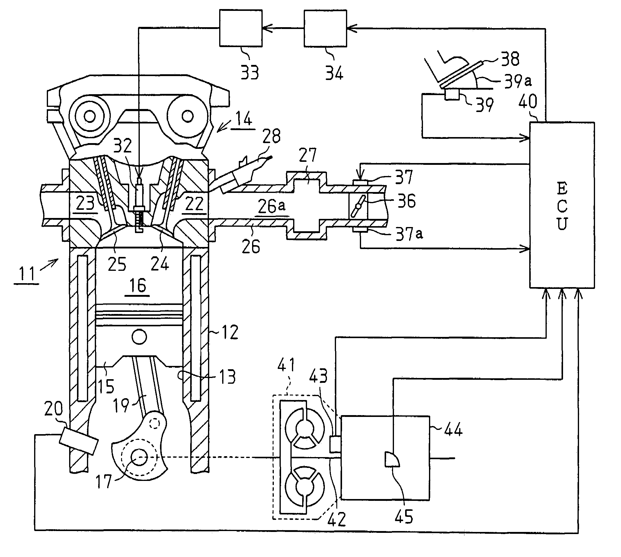
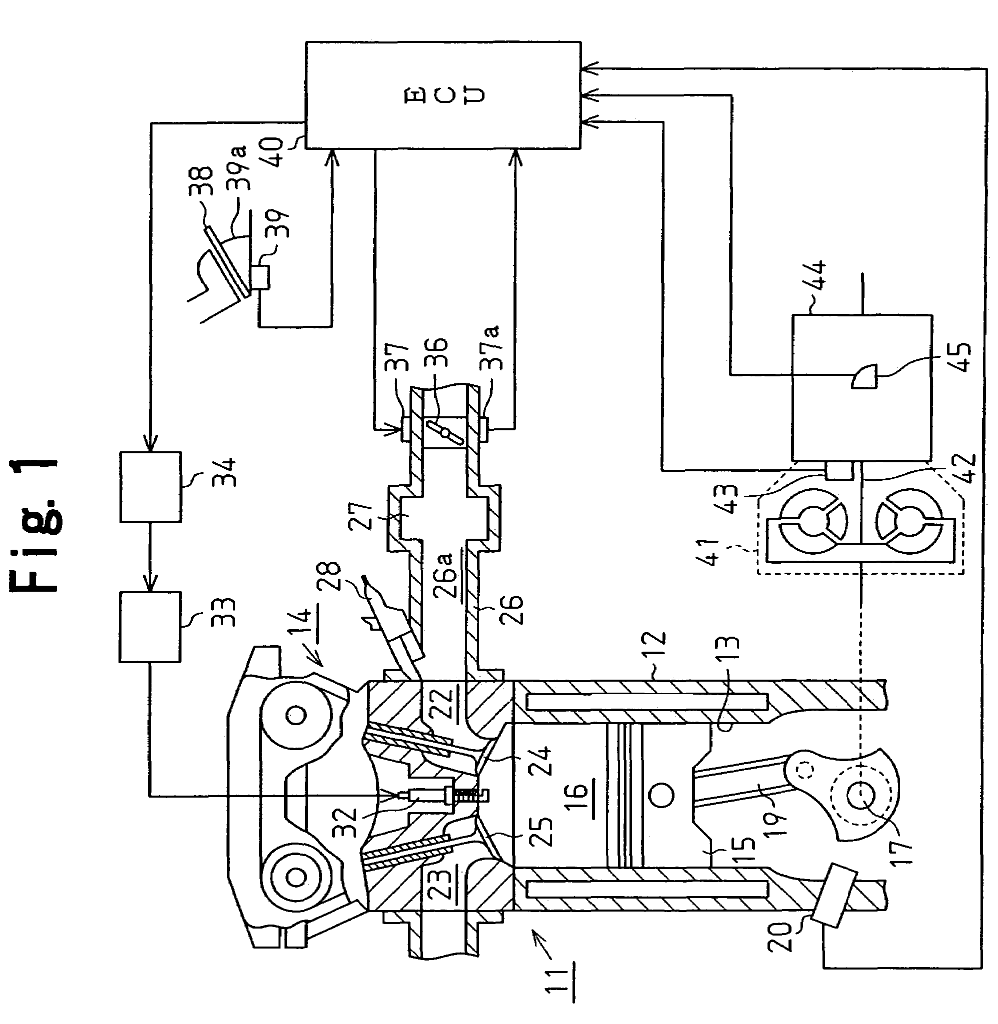
[0031]A throttle valve control apparatus for an internal combustion engine according to the present invention will now be described with reference to the drawings. The control apparatus is used for a gasoline engine 11 in this embodiment.
[0032]As shown in FIG. 1, the engine 11 has a cylinder block 12, in which cylinders 13 are formed. Each cylinder 13 accommodates a piston 15. The piston 15 reciprocates in the cylinder 13. A cylinder head 14 is placed on the top of the cylinder block 12. Each cylinder 13, the cylinder head 14, and the top surface of the associated piston 15 define a combustion chamber 16. The engine 11 includes an output shaft, which is a crankshaft 17, and connecting rods 19. Each connecting rod 19 corresponds to one of the pistons 15 and converts reciprocation of the piston 15 to rotation of the crankshaft 17.
[0033]An engine speed sensor 20 is provided in an outer wall of one of the cylinders 13. The engine speed sensor 20 is located in the vicinity of the cranksh...
eighth embodiment
[0135]A throttle opening degree control apparatus for an internal combustion engine according to the present invention will now be described with reference to FIGS. 17(a) to 18. The control apparatus is used for a gasoline engine 11 in this embodiment. The differences from the first embodiment will be mainly discussed.
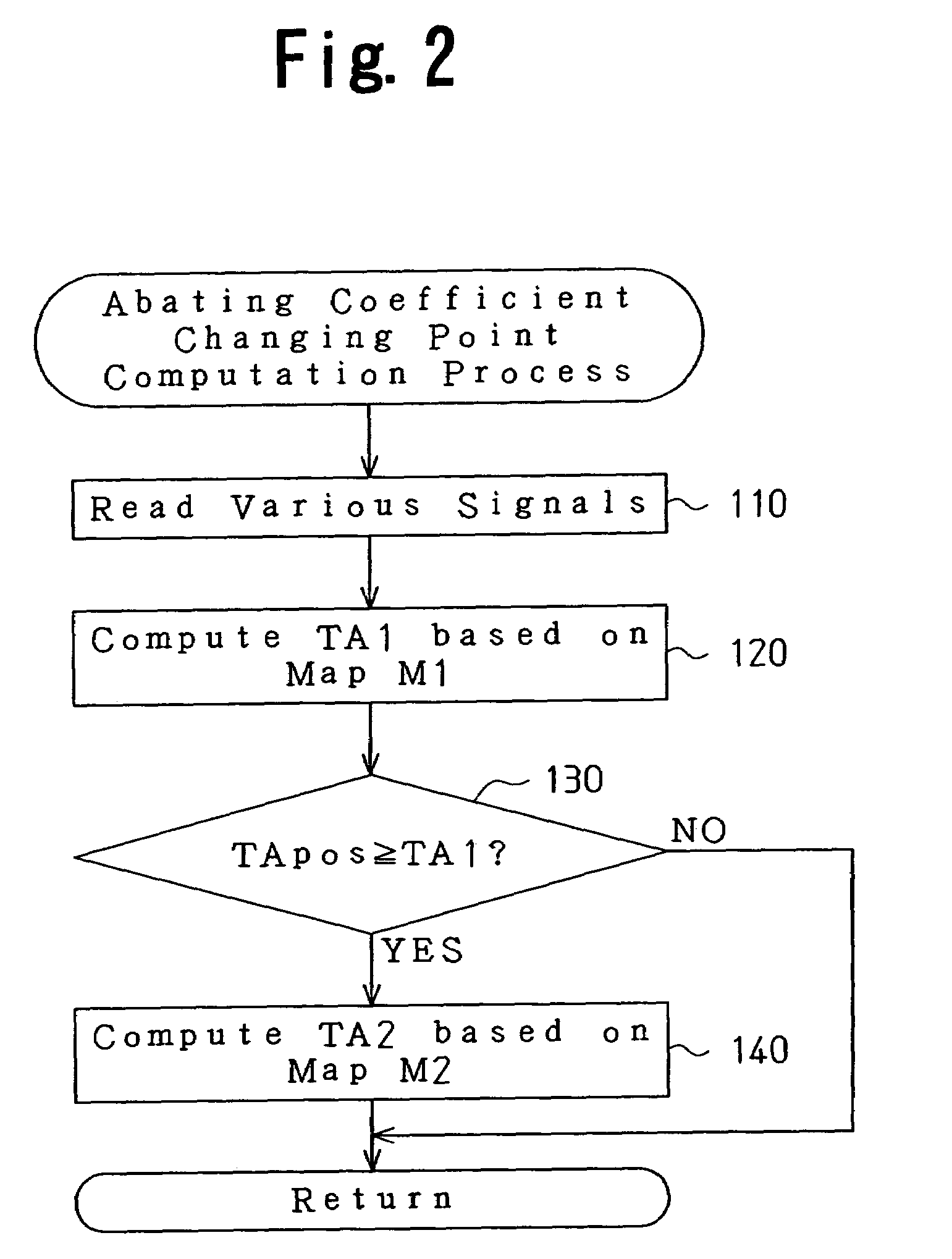
[0136]In the first embodiment, the first throttle opening degree TA1 and the second throttle opening degree TA1 are computed by referring to the abating coefficient changing point maps M1, M2. The first and second throttle opening degrees TA1, TA2 represent timing at which the abating coefficient is switched. To the contrast, in this embodiment, the first and second throttle opening degrees TA1, TA2 are independently set according to the gear of the automatic transmission 44 that is selected during the throttle opening control degree control. This embodiment has the following two objectives.
[0137]Demands for a throttle opening degree control vary depending on what gear...
ninth embodiment
[0147]A throttle opening degree control apparatus for an internal combustion engine according to the present invention will now be described with reference to FIG. 19. The control apparatus is used for a gasoline engine 11 in this embodiment. The differences from the fifth embodiment shown in FIGS. 13 and 14 will be mainly discussed.
[0148]In the fifth embodiment, the time limit TL4 is set as shown in FIG. 13 for the period from when the abating coefficient NSM is set to zero to when the abating control is terminated. To the contrast, the time limit is set for each gear in this embodiment. The objective is to satisfy demands in a throttle opening degree control related to each gear position. For example, a priority is assigned in the following manner when setting the time limit. That is, when the first gear is selected, a priority is assigned to the acceleration. When the second gear is selected, a priority is assigned to acceleration and a control for reducing shock due to accelerat...
PUM
 Abstract
Description
Claims
Application Information
 - R&D
- Intellectual Property
- Life Sciences
- Materials
- Tech Scout
- Unparalleled Data Quality
- Higher Quality Content
- 60% Fewer Hallucinations
Browse by: Latest US Patents, China's latest patents, Technical Efficacy Thesaurus, Application Domain, Technology Topic, Popular Technical Reports.
© 2025 PatSnap. All rights reserved.Legal|Privacy policy|Modern Slavery Act Transparency Statement|Sitemap|About US| Contact US: help@patsnap.com


