
Tool cabinet with a positioning device for drawers

Inactive Publication Date: 2006-05-23
LIU JUNG FENG
View PDF6 Cites 93 Cited by
  • Summary
  • Abstract
  • Description
  • Claims
  • Application Information

AI Technical Summary

Benefits of technology

[0008]The main objective of the present invention is to provide a tool cabinet with a positioning device for drawers, which overcomes the defects in prior art and has a simple structure.

Problems solved by technology

However, the drawers slide out too easily when the tool cabinet is moving such that the tools may be scattered over a floor, and worse, the center of gravity of the tool cabinet might be shifted such that it tips over and endangers workers.
However, both hands are required to open the drawer (63) which is inconvenient when in a workshop.
Furthermore, only one side of the drawer (63) is fastened and that side endures the total force from the drawer (63), whereby the elements are damaged easily.
What is more, the overall structure is complex such that it is unnecessarily expensive to fabricate and inclined to malfunction.

Method used


Image

  • Tool cabinet with a positioning device for drawers
  • Tool cabinet with a positioning device for drawers
  • Tool cabinet with a positioning device for drawers

Examples


Embodiment Construction

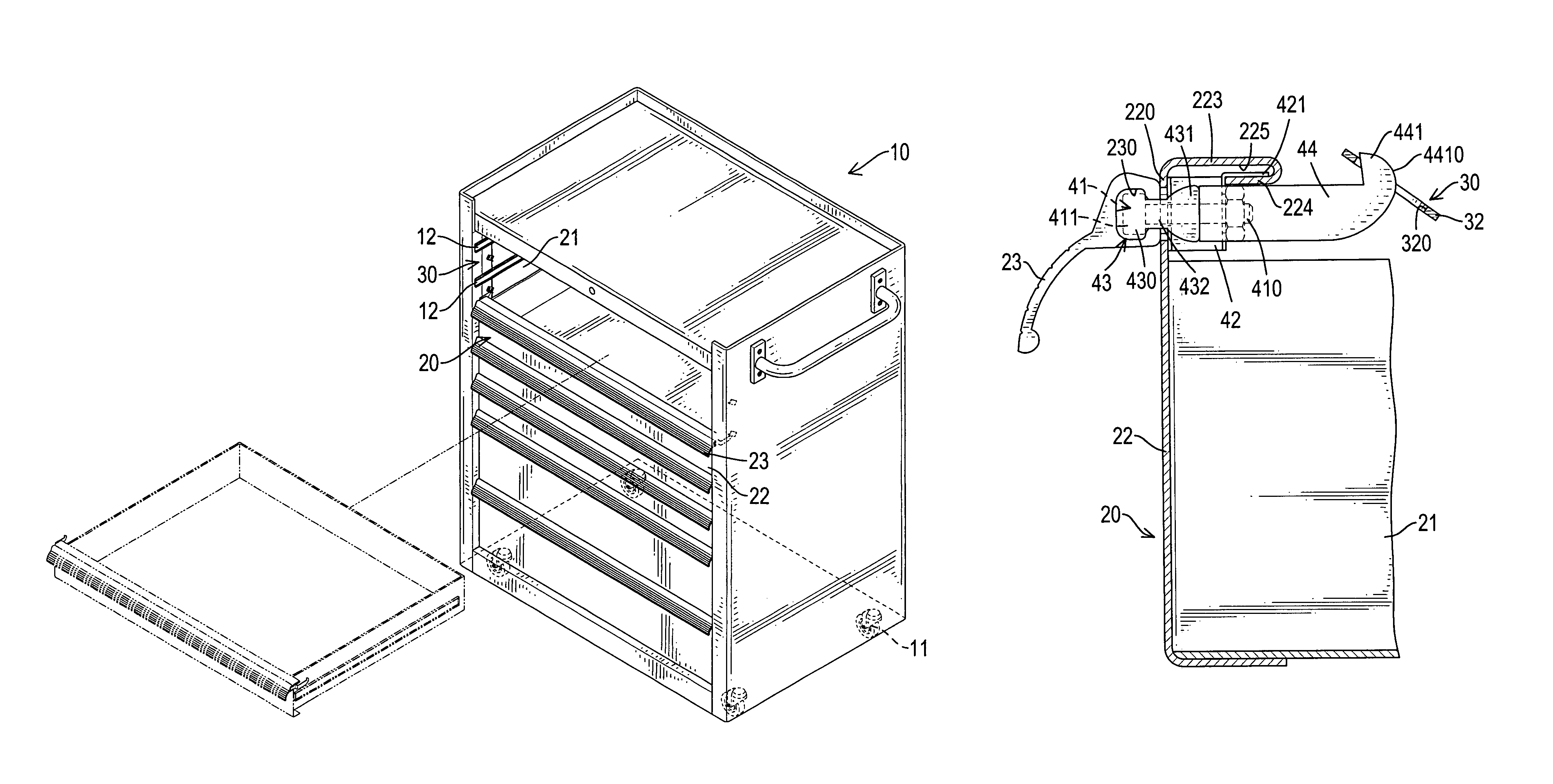
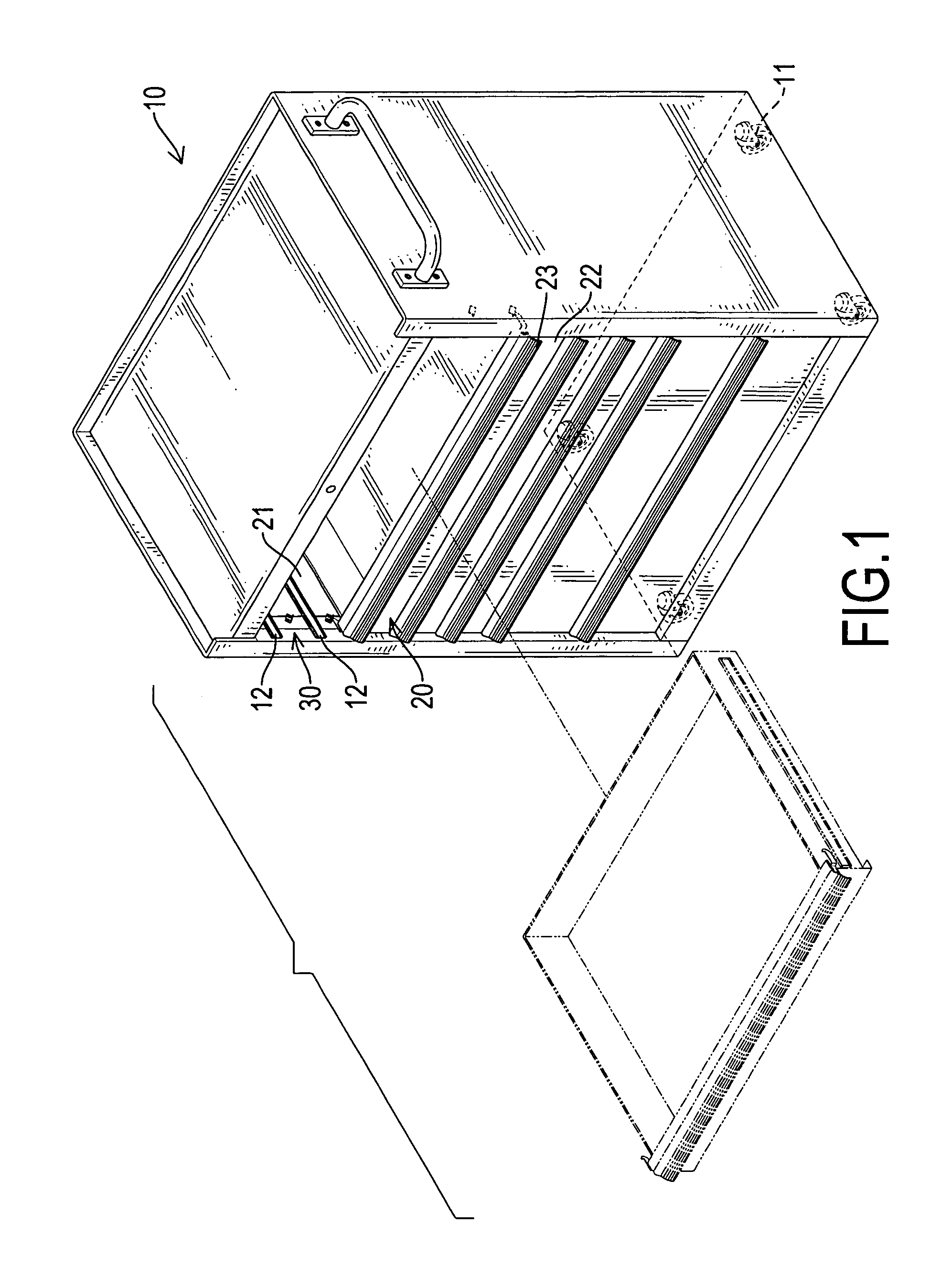
[0016]With reference to FIG. 1 and FIG. 2, a cabinet (10) has a body with an open front, multiple slide tracks (12) are mounted at inner walls of two opposite side faces of the body, and at least one drawer (20) is mounted between two opposite slide tracks (12). To fasten the drawers (20) in the cabinet (10), a positioning device is provided and comprises multiple locating devices (3) corresponding respectively to the drawers (20). Each locating device (3) is mounted between a corresponding drawer (20) and the inner walls of two opposite side faces. Multiple wheels (11) are mounted at a bottom of the cabinet (10).

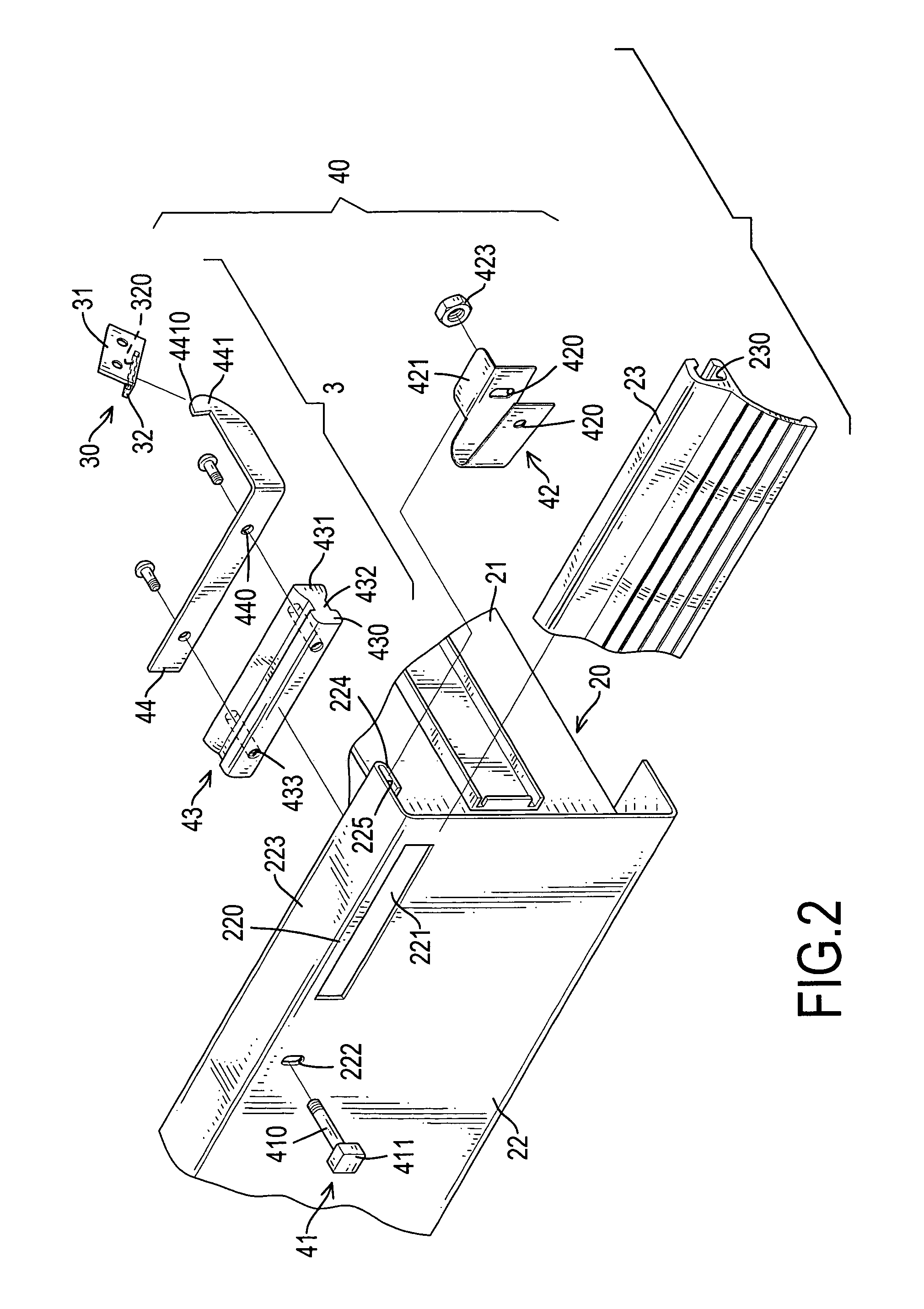
[0017]With reference to FIGS. 1–4, the drawer (20) has two side walls (21), a front wall (22), and a handle (23) crossing the front wall (22) transversely. Each locating device (3) includes a fastener (30), a fixture group (40) mounted in the front wall (22) of the corresponding drawer (20). Two slots (221) and two first holes (222) are defined in the front wall (22). The f...


PUM


Abstract

A cabinet has a positioning device including at least one locating device. Each locating device has a fastener, a fixture group, two slots and two first holes. The fastener has a side board and a bottom board forming an L-shape, and a notch is defined in the bottom board. The fixture group includes a bridge member and a lever, and the bridge member is connected with an arm. A hook is formed in the distal end of the arm, which can further hitch itself to the channel of the fastener. When the handle of the drawer is swayed outward by the user and the hook will escape from the channel, and the drawer will open.

Description

BACKGROUND OF THE INVENTION[0001]1. Field of the Invention[0002]The present invention relates to a tool cabinet, and particularly relates to a tool cabinet with a positioning device for drawers to prevent the drawers from undesirably sliding out.[0003]2. Description of Related Art[0004]A tool cabinet is used for storing various tools, and the tool cabinet with wheels can be moved conveniently if necessary. Normally, a slide track is mounted between the drawers and the cabinet to facilitate opening and closing of the drawers. However, the drawers slide out too easily when the tool cabinet is moving such that the tools may be scattered over a floor, and worse, the center of gravity of the tool cabinet might be shifted such that it tips over and endangers workers. In order to enhance safety, the drawers are designed to be locked. As shown in FIG. 6, two slide tracks (62) are respectively mounted on two opposite walls of a tool cabinet (61), and a drawer (63) has two horizontal flanks (...

Claims


Application Information

Patent Timeline
IPC IPC(8): A47B88/00A47B95/02
CPCB25H3/028E05B65/46E05C3/14A47B2095/024
Inventor LIU, JUNG-FENG
Owner LIU JUNG FENG
Learn More