
Apparatus comprising expandable bistable tubulars and methods for their use in wellbores

Inactive Publication Date: 2006-05-23
SCHLUMBERGER TECH CORP
View PDF24 Cites 18 Cited by
  • Summary
  • Abstract
  • Description
  • Claims
  • Application Information

AI Technical Summary

Benefits of technology

[0006]According to one aspect of the present invention, a technique is provided for connecting tubulars, such as those used within a wellbore. The technique is particularly amenable to use with expandable tubulars. The technique allows such expandable tubulars to be connected and yet expanded as desired. Certain connectors utilized with this technique are particularly helpful in connecting tubulars formed of bistable cells that facilitate expansion of the tubular from a contracted stable state to an expanded stable state.

Problems solved by technology

With these types of tubulars in particular, the connection of one tubular to another becomes difficult.
Connectors or connection systems designed for conventional tubulars do not readily adapt to tubular members that are expanded.

Method used


Image

  • Apparatus comprising expandable bistable tubulars and methods for their use in wellbores
  • Apparatus comprising expandable bistable tubulars and methods for their use in wellbores
  • Apparatus comprising expandable bistable tubulars and methods for their use in wellbores

Examples


Embodiment Construction

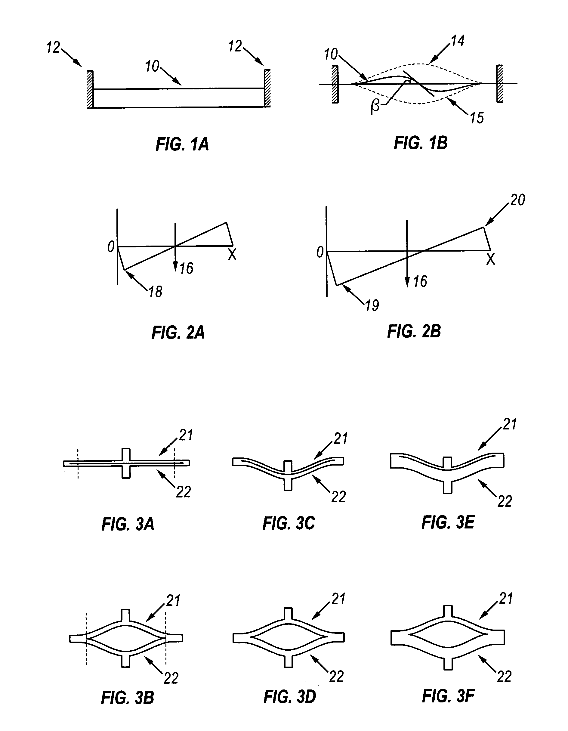
[0037]Bistable devices used in the present invention can take advantage of a principle illustrated in FIGS. 1A and 1B. FIG. 1A shows a rod 10 fixed at each end to rigid supports 12. If the rod 10 is subjected to an axial force it begins to deform as shown in FIG. 1B. As the axial force is increased rod 10 ultimately reaches its Euler buckling limit and deflects to one of the two stable positions shown as 14 and 15. If the buckled rod is now clamped in the buckled position, a force at right angles to the long axis can cause the rod to move to either of the stable positions but to no other position. When the rod is subjected to a lateral force it must move through an angle β before deflecting to its new stable position.

[0038]Bistable systems are characterized by a force deflection curve such as those shown in FIGS. 2A and 2B. The externally applied force 16 causes the rod 10 of FIG. 1B to move in the direction X and reaches a maximum 18 at the onset of shifting from one stable configu...


PUM


Abstract

At least a first expandable tubular and a second expandable tubular are connected to each other by a connector system. The connector system is expandable and utilizes a plurality of extensions that may be used to create an interlocking engagement. The system design enables both the tubulars and the connector system to be expanded to an increased diameter.

Description

CROSS REFERENCE TO RELATED APPLICATIONS[0001]This is a divisional of application Ser. No. 10 / 035,994, filed Dec. 26, 2001, now U.S. Pat. No.: 6,648,071, issued Nov. 18, 2003, which claims the benefit under 35 USC 119(e) to U.S. Provisional Application Ser. No.: 60 / 263,934, filed Jan. 24, 2001.FIELD OF THE INVENTION[0002]This invention relates to equipment that can be used in the drilling and completion of wellbores in an underground formation and in the production of fluids from such wells, and particularly to connection systems for connecting a variety of tubulars used in wellbores.BACKGROUND OF THE INVENTION[0003]Fluids such as oil, natural gas and water are obtained from a subterranean geologic formation (a “reservoir”) by drilling a well that penetrates the fluid-bearing formation. Once the well has been drilled to a certain depth the borehole wall must be supported to prevent collapse. Conventional well drilling methods involve the installation of a casing string and cementing ...

Claims


Application Information

Patent Timeline
IPC IPC(8): E21B43/08E21B43/10F16B5/07E21B17/00E21B17/02E21B17/04F16L37/098
CPCE21B17/00E21B17/02E21B17/04E21B43/103E21B43/105E21B43/106F16L37/098E21B43/108Y10T403/557Y10T403/5761Y10T403/7051Y10T403/5773Y10T403/7045
Inventor HACKWORTH, MATTHEW R.JOHNSON, CRAIG D.BIXENMAN, PATRICK W.
Owner SCHLUMBERGER TECH CORP
Learn More