
Data storage device and actuator control method

a data storage device and actuator technology, applied in the direction of data recording, magnetic recording, instruments, etc., can solve the problems of capacitors that cannot always obtain enough power, cannot obtain a sufficiently large back electromotive force from voice coil motors, and capacitors that cannot supply power to retract drivers, etc., to achieve effective control and restrict the effect of the actuator turning rang

Inactive Publication Date: 2006-05-16
WESTERN DIGITAL TECH INC
View PDF2 Cites 12 Cited by
  • Summary
  • Abstract
  • Description
  • Claims
  • Application Information

AI Technical Summary

Benefits of technology

The patent text describes a data storage device with a magnetic head slider that can be controlled to move the head to a target position. The actuator, which holds the head, operates to move the head to the target position. However, the bouncing off the outer crash stop can be significant, causing the actuator to bounce off the ramp and drop to the magnetic disk. To address this problem, the patent proposes a solution that controls the actuator based on the temperature, reducing the bouncing amount and ensuring a smooth retracting operation. The actuator control section can also use a capacitor to accumulate power and control the actuator's movement. Overall, the patent aims to improve the hard disk drive's seek speed, vibration / shock resistance, and compactness.

Problems solved by technology

In particular, if the disk size is small or the rotation speed is low, it may be impossible to obtain a sufficiently large back electromotive force from the voice coil motor to retain the actuator on the ramp by acting against the repelling force given to the actuator by the collision.
Using a capacitor to supply power to the retract driver is also not free from this problem since the charge accumulated in the capacitor is limited.
Utilizing the back electromotive force together with this capacitor cannot always obtain enough power.
On the other hand, if the retracting drive force is too small, the tab cannot climb over the inclined surface of the ramp, which lets the magnetic head drop to the magnetic disk.

Method used


Image

  • Data storage device and actuator control method
  • Data storage device and actuator control method
  • Data storage device and actuator control method

Examples


Embodiment Construction

[0039]Specific embodiments of the present invention will be described below. Although embodiments of the present invention are described, the present invention is not limited to these embodiments. To facilitate clear understanding, omission and simplification are done, where appropriate, in the following description and in the drawings. Those skilled in the art can easily make modifications, additions and alterations to the individual elements of these embodiments without departing from the scope of the present invention.

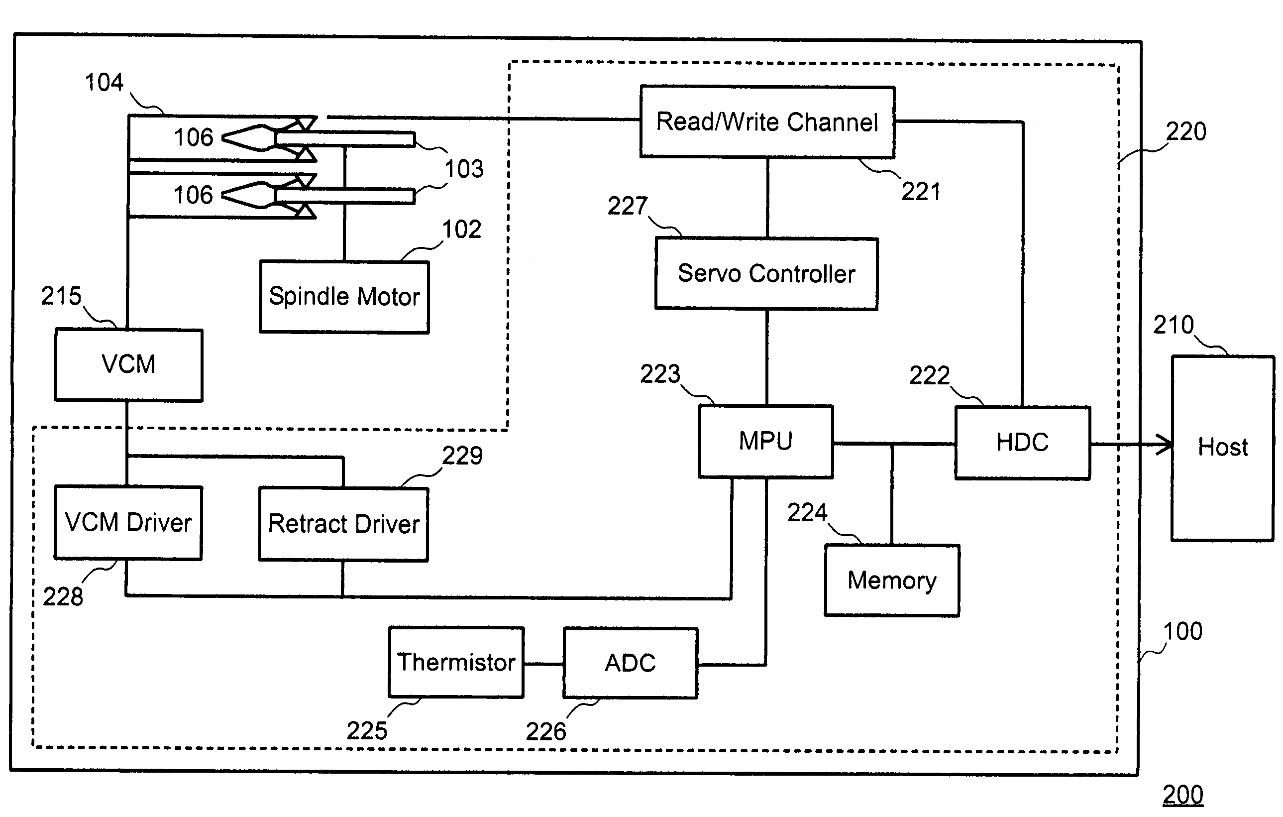
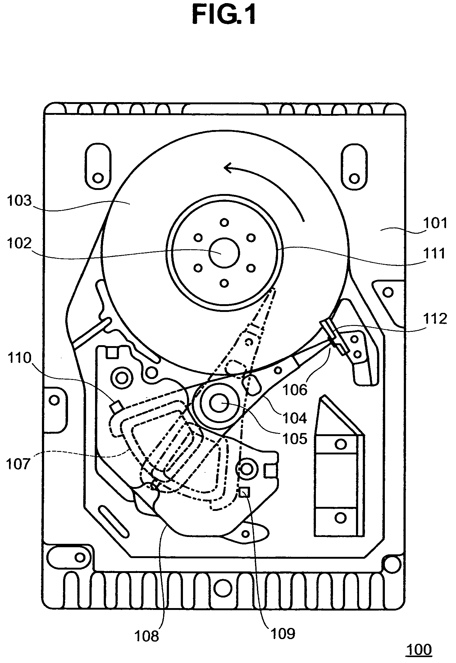
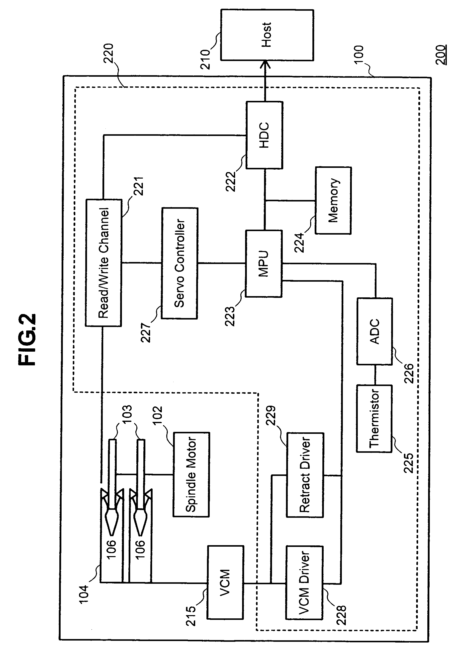
[0040]FIG. 1 shows the configuration of an embodiment of a hard disk drive 100 in accordance with the present invention. The hard disk drive 100 has each component accommodated in a disk enclosure. The disk enclosure is composed of a base 101 and a cover (not shown). The base 101 is a box whose top is open. This top opening is closed by the cover. In the disk enclosure, a spindle motor 102 is located on the base 101 and one or a plurality of magnetic disks 103 are h...


PUM

PropertyMeasurementUnit
temperaturesaaaaaaaaaa

Abstract

Embodiments of the invention prevent the magnetic head from dropping to the magnetic disk when it is retracted. If the power supply Vcc to the drive is interrupted, a power supply voltage detecting section detects that the power supply to the drive is interrupted. A control section sets switches to the ON state in order to discharge the charged retract capacitor and supply the discharge current to a voice coil. The control section retains the switches in the ON state for a period which is determined based on the discharge period specifying control data stored in a register and the count signal from a counter. A voice coil motor, to which the current is supplied, turns the actuator in the unloading direction to retract the actuator to the ramp.

Description

CROSS-REFERENCES TO RELATED APPLICATIONS[0001]Not ApplicableBACKGROUND OF THE INVENTION[0002]The present invention relates to data storage devices and actuator control methods. More particularly, the invention relates to a data storage device and actuator control method for providing actuator control suited for retraction.[0003]Various apparatus using optical disks, magnetic tapes and other types of media have been known as information recording and reproducing apparatus. Among them, the hard disk drive is popular as a storage device for computers so widely that it is one of the storage devices indispensable for today's computer systems. Further, not limited to computers, the hard disk drive is increasingly enlarging its area of application due to its superior characteristics including moving picture recording and reproducing apparatus and removable memories used in car navigation systems, digital cameras, etc.[0004]A hard disk drive has a magnetic disk on which data is recorded, a ...

Claims


Application Information

Patent Timeline
Patent Type & Authority Patents(United States)
IPC IPC(8): G11B21/02G11B5/596G11B5/54G11B21/12
CPCG11B21/12G11B5/54
Inventor KURAMOTO, KENICHIKAWAKAMI, TAKANORI
Owner WESTERN DIGITAL TECH INC
Learn More