
Polarization scrambler and a method for polarization scrambling

a polarization scrambler and polarization technology, applied in the field of polarization scrambler and polarization scrambler, can solve problems such as adversely affecting high-speed optical data transmission

Inactive Publication Date: 2006-05-16
SIEMENS AG
View PDF1 Cites 6 Cited by
  • Summary
  • Abstract
  • Description
  • Claims
  • Application Information

AI Technical Summary

Benefits of technology

"The patent describes a solution for scrambling the polarization of light using a special device called a polarization scrambler. This scrambler can be controlled using electrical signals to change the way the light is polarized. The technical effect of this invention is that it allows for better control over the polarization of light, which can be useful in various applications such as optical communication systems."

Problems solved by technology

Polarization mode dispersion, referred to as PMD, adversely affects high-speed optical data transmission.
At least for certain input polarizations, the output polarizations which are produced define, however, only a two-dimensional, and not a three-dimensional, figure within the Poincaré sphere since depolarization is a necessary but not necessarily sufficient precondition for output polarizations actually being produced which define a three-dimensional figure, and not just a two-dimensional figure, within the Poincaré sphere.

Method used


Image

  • Polarization scrambler and a method for polarization scrambling
  • Polarization scrambler and a method for polarization scrambling
  • Polarization scrambler and a method for polarization scrambling

Examples


Embodiment Construction

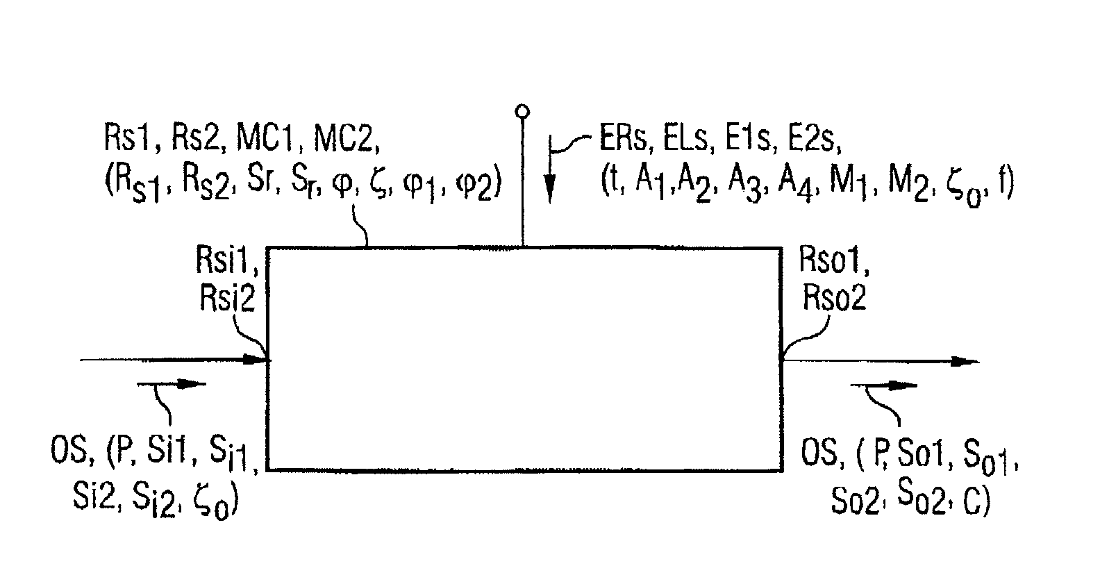
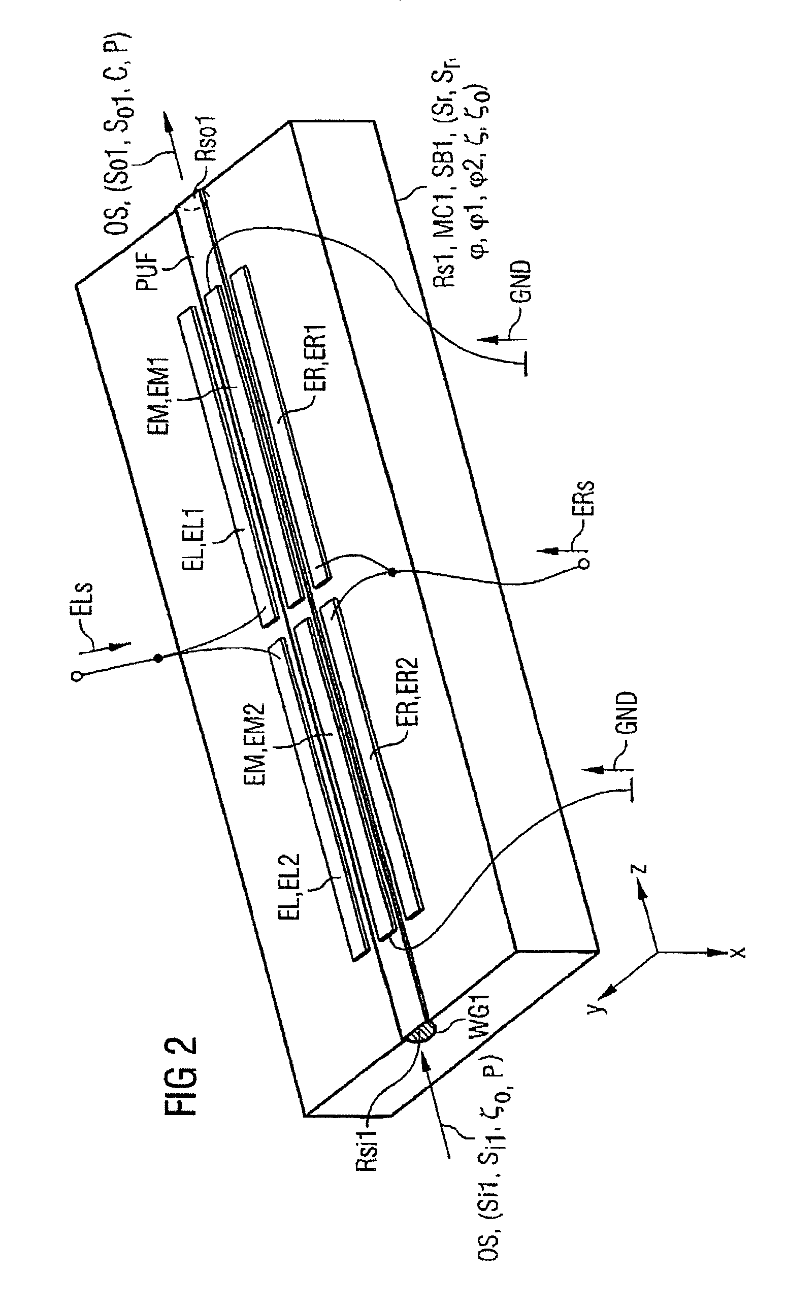
[0017]Without any restriction to generality, the following text regards all retarders as being loss-free, although the principle according to the present invention is also applicable to lossy retarders. Retarders each have a pair of mutually orthogonally polarized eigen modes. To assist understanding, one of the two eigen modes is, in each case, referred to as the reference eigen mode in the following text. It is sufficient to quote the reference eigen mode instead of both eigen modes, since the other eigen mode is simply the polarization orthogonal to it. Any other eigen mode is subject to a phase delay in the retarder which is greater by the so-called delay of the retarder than that of the reference eigen mode, which is normally identified or defined by this statement as the reference eigen mode. It is sufficient to consider delays in the main interval, π . . . π since the effect of two delays which differ by an integer multiple of 2π is identical.

[0018]It is even possible to go o...


PUM

PropertyMeasurementUnit
orientation angleaaaaaaaaaa
frequencyaaaaaaaaaa

Abstract

A polarization scrambler and associated method for polarization scrambling are provided, wherein light is passed through a retarder whose eigen modes and delay vary with time and which is driven with alternating signals at two harmonic frequencies. One exemplary embodiment with an electrooptical wave plate operates with a horizontal or vertical input polarization and supplies output polarizations which vary with time and have uncorrelated normalized Stokes parameters. The polarization scrambler which is produced can be used in devices for detection of polarization mode dispersion.

Description

BACKGROUND OF THE INVENTION[0001]Polarization mode dispersion, referred to as PMD, adversely affects high-speed optical data transmission. A method for measurement of polarization mode dispersion has been described in the Conference Proceedings of the European Conference on Optical Communication, Amsterdam, NL, Sep. 30–Oct. 4, 2001, Tu.A.3.4, in which a polarization scrambler is used which can produce a large number of output polarizations, or all possible output polarizations, from a specific input polarization. The output polarizations which can be produced define a three-dimensional, not just two-dimensional, figure within the Poincaré sphere. Further polarization scramblers are described in Electronics Letters, Volume 30 (1994)18, pages 1500–1501. These can produce a depolarized output signal from any given input polarization. At least for certain input polarizations, the output polarizations which are produced define, however, only a two-dimensional, and not a three-dimensional...

Claims


Application Information

Patent Timeline
Patent Type & Authority Patents(United States)
IPC IPC(8): G02F1/03G02F1/07G02F1/01
CPCG02F1/0136
Inventor NOE, REINHOLDSANDEL, DAVID
Owner SIEMENS AG
Learn More