System and method for pipeline reliability management

Inactive Publication Date: 2006-05-09
ARIZONA PUBLIC SERVICE
View PDF7 Cites 12 Cited by
  • Summary
  • Abstract
  • Description
  • Claims
  • Application Information

AI Technical Summary

Benefits of technology

[0017]The present invention provides, inter alia, a system and method for facilitating the forecasting of pipeline and pipe system reliability to effectively manage maintenance, repair, and replacement costs over the long term. The system and method may be employed in the design, installation, testing, and operational phases of new pipelines, for instance, to maximize service life.
[0018]In specific embodiments, the present invention provides a method of facilitating the determination of whether to take pipe management action such as repairing or replacing pipe. The method generally includes (in any order) the steps of: acquiring a first parameter (e.g., a design parameter for the pipe, such as the diameter); inspecting the pipe a first time; acquiring a second parameter (e.g., an evaluation of the structural integrity of the pipe); and acquiring a third parameter (e.g., a pressure within the pipe, which may be the maximum pressure anticipated in future service). The method generally also includes the step of: using at least a relation (e.g., a graph) of the evaluation of the structural integrity of the pipe and the pressure within the pipe, facilitating a determination of whether or not to take pipe management action. When the pipe management action should be taken may also be determined.
[0022]In another embodiment, the present invention further provides a system for facilitating a determination of whether to take pipe management action. The system generally includes a relation of pressure versus a quantification of the degradation of the structural integrity of the pipe. Similar to as described above for the method, the relation may be either a physically-viewable graph or embedded within a computer, such as an algorithm, data, or a combination thereof. The relation may have a zone of higher risk and a zone of lower risk, and may also have a zone of medium risk.

Problems solved by technology

For example, pipes in industrial cooling water processes and municipal water systems installed over the past 20 to 50 years are aging and the degradation of these pipes may be related to inadequate design, manufacturing defects, improper installation, or simply the pipes approaching the end of their useful life.
Such degradation may lead to pipeline or system failures, which may result in costly unplanned outages or down times.
In general, pipelines were typically not maintenanced regarding their structural integrity until a failure occurred, at which time either the failed section, or the entire pipeline, would be replaced.
Pipelines may have been inspected at planned outages, at which time obvious problems were typically repaired.
However, systematic methods of managing pipe, pipelines, or pipe systems were typically not used to anticipate failures and attempt to conduct preventative maintenance or replace the pipe before failure occurs.
However, the previous approach of fixing the pipe when it breaks may not be acceptable such as in cases in which a burst pipe may result in damage to property or injury to people, or where loss of the process fluid would have deleterious environmental consequences.
However, since the wire 111 may be so highly stressed, if the wire 111 slightly deteriorates, the wire 111 may break.
In most applications, one or even several wire breaks may occur without failure of the pipeline; however, if enough wires 111 break, the pipeline may fail.
However, this model often resulted in overly conservative and expensive pipe management practices, which resulted in, for example, the replacing of pipe that could have remained in service for some time.
The engineers often determined that the hollow areas in the pipe wall were areas of concrete failure.
As can be appreciated, uncovering buried pipelines for periodic inspection of the outside 122 may also be cost prohibitive.

Method used


Image

  • System and method for pipeline reliability management
  • System and method for pipeline reliability management
  • System and method for pipeline reliability management

Examples


Embodiment Construction

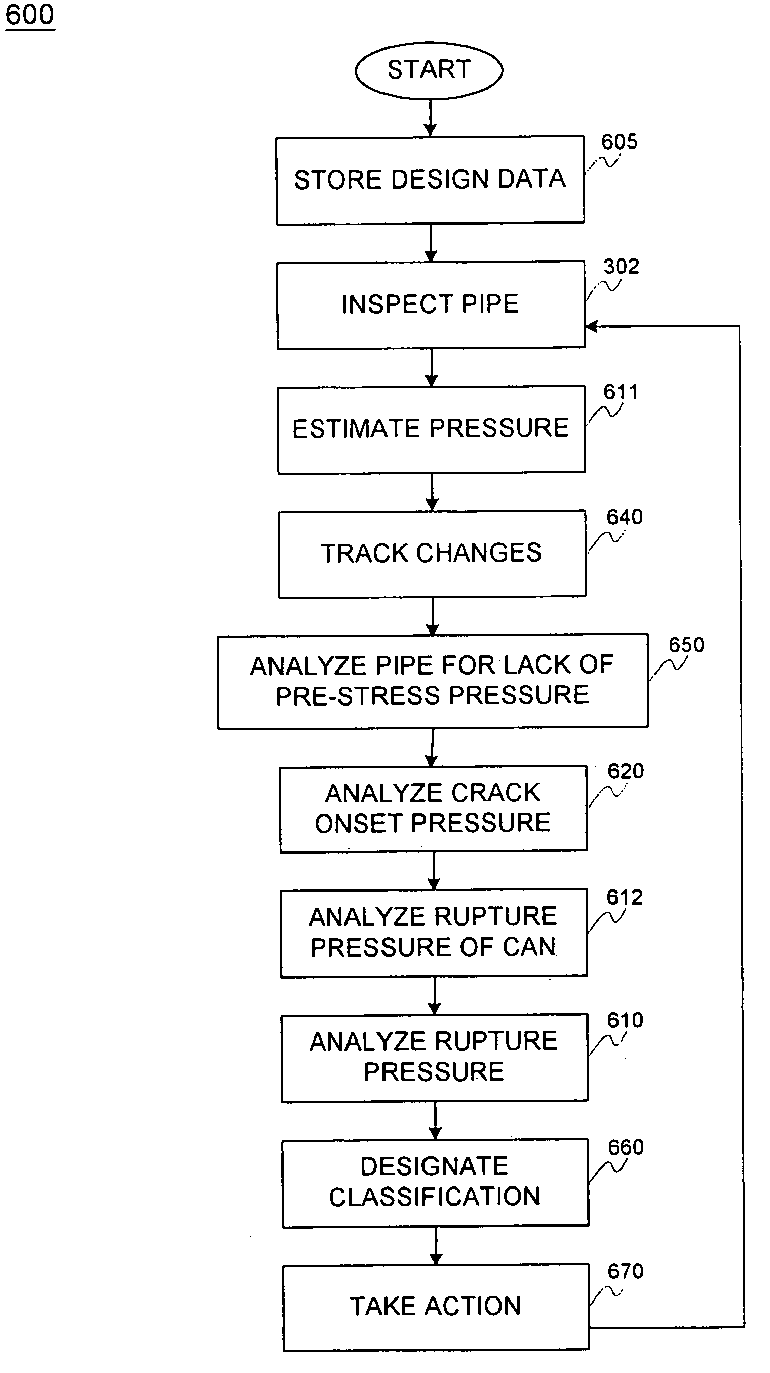
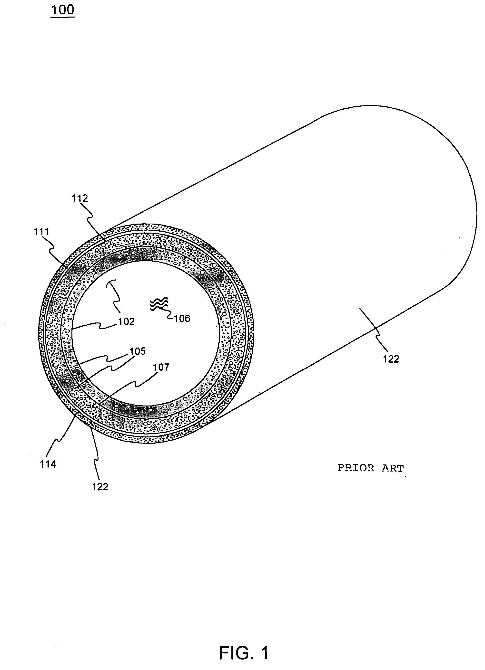
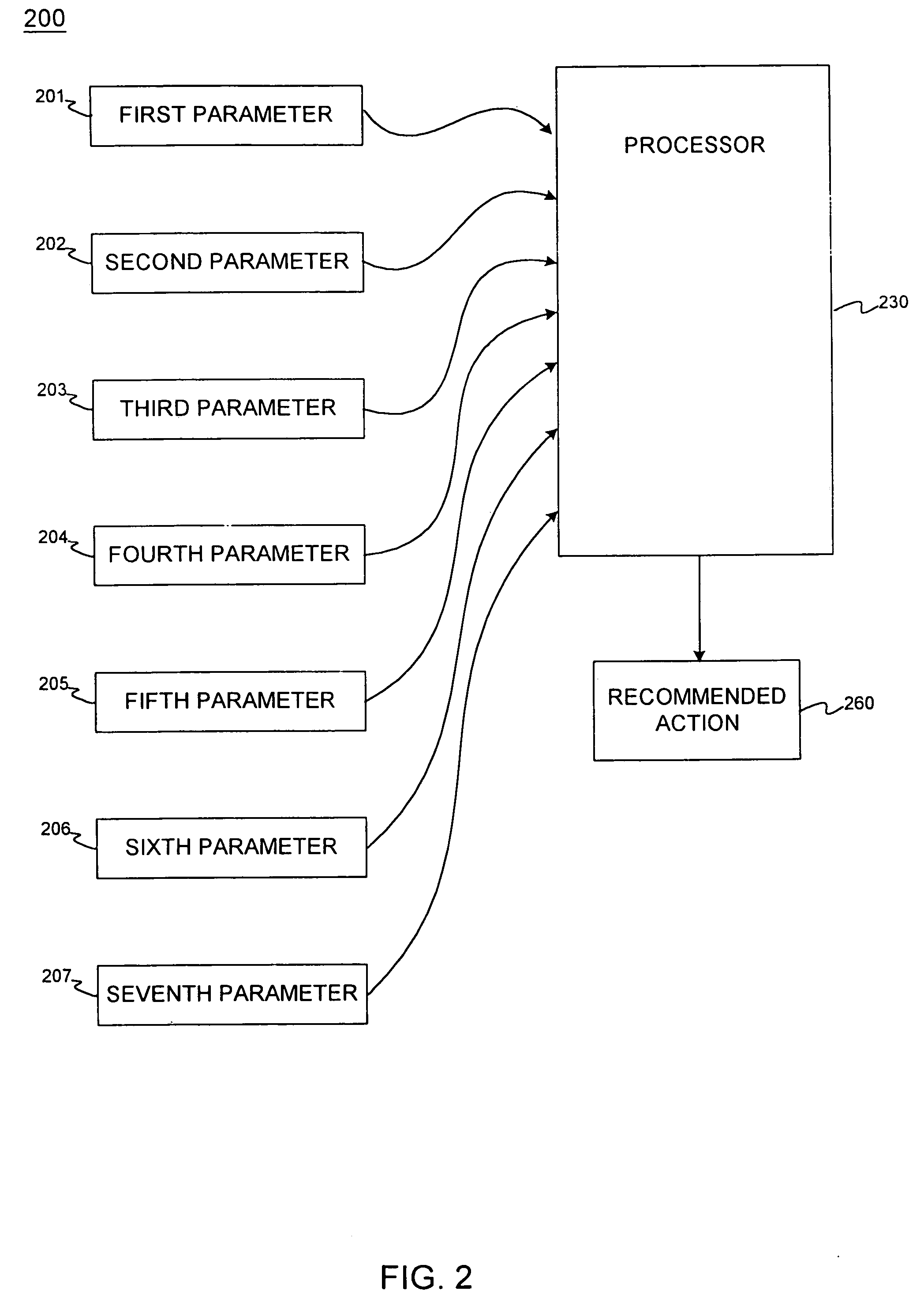
[0037]The present invention includes systems and methods for analyzing the reliability and replacement of components, and more specifically, to a forecasting and reliability management tool for a utility network, such as a pipeline network or pipe system. As such, while the system and methods shall be described in relation to a pipeline or pipe system, one skilled in the art will appreciate that much of the functionality is applicable to other components, utilities, networks and / or the like. For example, at least certain aspects of the present system and method may be applied to any portion of roads, canals, sewer systems, power lines, railroad tracks, buildings, circuits, fences, walls or any other system with components that may fail or degrade. The present invention may also be applicable to heat exchanger tube inspections and monitoring pipelines for erosion or corrosion.

[0038]In this regard, the present invention may be described herein in terms of functional block components a...


PUM


Abstract

A system and method is disclosed for facilitating the management of pipeline reliability, maintenance, repair, and / or replacement. Embodiments may be computer-implemented, and may be suitable for prestressed concrete cylinder pipe (e.g., PCCP). Method steps include inspecting the pipe and storing or inputting design and inspection parameters, as well as the maximum expected pressure within the pipe. A relation of pressure versus degradation (e.g., number of broken wires) may be used, which may have zones of risk or classifications corresponding to pipe management actions. The pipe may be analyzed for lack of prestress over various portions of circumference and length. The pipe rupture pressure, crack onset pressure, or can rupture pressure may be analyzed and compared to the expected pressure. The method may be tested and the inspection repeated while tracking changes. The action may involve, for instance, doing nothing, monitoring the pipe, repairing the pipe, or replacing the pipe.

Description

REFERENCE TO RELATED APPLICATIONS[0001]This application is a Continuation of U.S. Ser. No. 10 / 093,620, now abandoned, filed Mar. 2002, and entitled “SYSTEM AND METHOD FOR PIPELINE RELIABILITY MANAGEMENT”,FIELD OF INVENTION[0002]This invention relates generally to systems and methods for analyzing the reliability and need for replacement of components, and more specifically, to a forecasting tool for a utility network, such as a pipeline network.BACKGROUND OF THE INVENTION[0003]As used herein, a pipe includes a cylindrical structure or tube that fluids, such as water, oil, or gas, can flow through. Further, also as used herein, a pipeline typically may include a plurality of discrete sections of pipe arranged in series so that the fluid may flow through the pipeline, through each section in turn, for instance, from one end of the pipeline to the other. In addition, as used herein, a pipe system may include a plurality of sections of pipe arranged as needed or desired to perform the i...

Claims


Application Information

Patent Timeline
IPC IPC(8): G01B3/44G01B3/52G05B23/02
CPCF17D5/00
Inventor PITTALWALA, SHABBIR H.WITTAS, DANIEL J.
Owner ARIZONA PUBLIC SERVICE
Why Eureka
Try Eureka