
Energy conditioning structure

a technology of energy conditioner and structure, applied in the direction of feed-through capacitor, aperture leaage reduction, fixed capacitor details, etc., can solve the problems of limiting the performance of critical and non-critical electronic circuitry, exacerbate the noise byproduct, and propagating energy portions utilizing prior art passive devices may experience increased levels of energy parasitic interferen

Inactive Publication Date: 2006-05-09
X2Y ATTENTUATORS
View PDF472 Cites 45 Cited by
  • Summary
  • Abstract
  • Description
  • Claims
  • Application Information

AI Technical Summary

Problems solved by technology

Today, as the density of electronics within typical system applications increases, unwanted noise byproducts of the increased density limit the performance of critical and non-critical electronic circuitry.
This antenna-analogous performance may exacerbate the noise byproduct problem in that, at higher frequencies, propagating energy portions utilizing prior art passive devices may experience increased levels of energy parasitic interference, such as various capacitive and / or inductive parasitics.
These increases can be due, in part, to the combination of constraints due to the functionally and / or structurally limitations of prior art solutions, coupled with the inherent manufacturing and / or design imbalances and / or performance deficiencies of the prior art.

Method used


Image

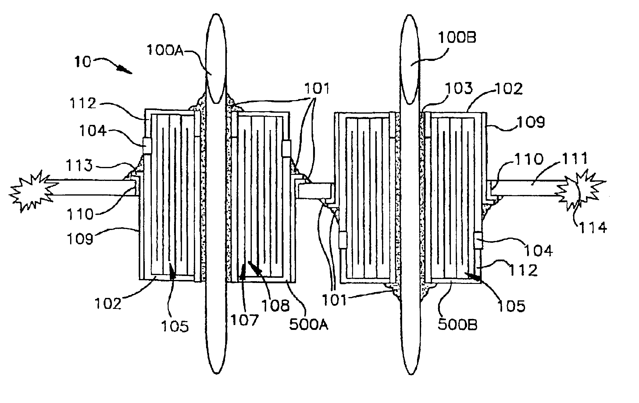
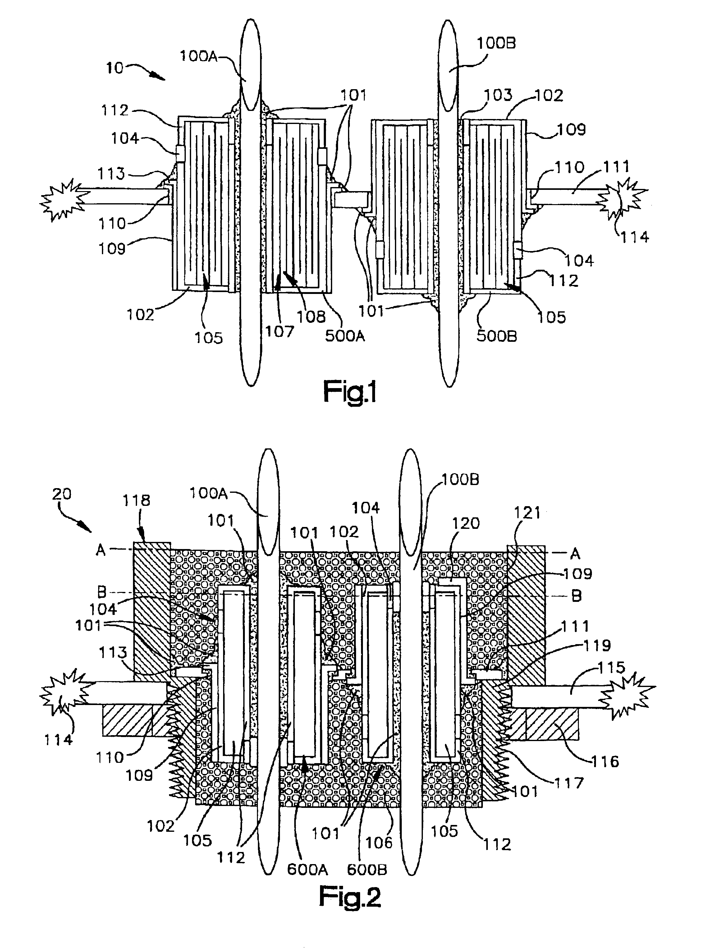
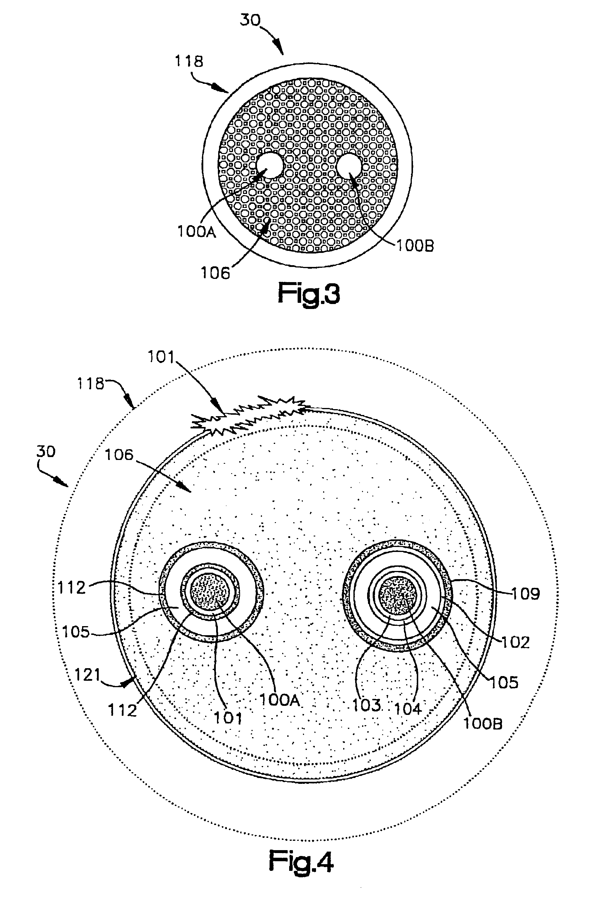
  • Energy conditioning structure
  • Energy conditioning structure
  • Energy conditioning structure

Examples


Embodiment Construction

[0011]In electricity it is common for various interactions and interrelationships between energy propagations to be described in terms of their complementary dynamics brought about by pairs or pairings of energy portion elements with opposing energies and forces that are interacting from a charged-polarized opposition or electrically opposite, but electrically complementary state to each other.

[0012]The interactions that are described herein as dynamic events, in complementary balance, occur by symmetry of pairings and are happening simultaneously, with the same or complementary, mirror-like, reverse positioning of elements such that certain timings of events occur, or are made with the understanding that the one skilled in the art is aware that man-made tolerances and / or limitations used to described or record certain dynamics, while usually done in terms of exacting words or wording meanings, will not always have full applicability to fully describe the matter at hand within the l...


PUM


Abstract

An energy conditioning structure comprised of any combination of multilayer or monolithic energy conditioners with operable conductors, all selectively arranged and shielded for attachment to at least a conductive substrate.

Description

CROSS REFERENCE TO RELATED APPLICATIONS[0001]This application is a continuation-in-part of application No. 10 / 190,889 filed Jul. 8, 2002, now U.S. Pat. No. 6,563,688, which is a continuation-in-part of co-pending application No. 09 / 815,246 filed Mar. 22, 2001, now U.S. Pat. No. 6,469,595, and application Ser. No. 09 / 815,246 filed Mar. 22, 2001 claims the benefit of U.S. provisional application 60 / 191,196 filed Mar. 22, 2000, provisional application 60 / 200,327 filed Apr. 28, 2000, provisional application 60 / 215,314 filed Jun. 30, 2000, and provisional application 60 / 225,497 filed Aug. 15, 2000.TECHNICAL FIELD[0002]This invention relates to a multi-functional energy conditioner whose physical architecture suppresses unwanted electromagnetic emissions, both those received from other sources and those created internally within electronic circuitry by differential and common mode currents. In addition, over voltage surge protection and magnetic properties are integrally incorporated with...

Claims


Application Information

Patent Timeline
Patent Type & Authority Patents(United States)
IPC IPC(8): H01G4/35H01C1/14H01C7/102H01L23/498H01L23/50H01L23/552H03H1/00H03H7/01H05K1/14H05K1/16H05K3/34H05K9/00
CPCH01G4/35H01L23/49827H01L23/50H01L23/552H05K9/0018H05K9/0039H01L2223/6622H01L2924/3011H05K1/141H01L2924/0002H05K1/162H05K3/3436H01L2924/00
Inventor ANTHONY, ANTHONYANTHONY, WILLIAM
Owner X2Y ATTENTUATORS
Learn More