
Wireless repeater for sensor system

a sensor system and repeater technology, applied in repeaters/relay circuits, transmission monitoring, instruments, etc., can solve the problems of occupants and structures being at risk, fires, gas leakages, etc., and extending the range of the system, so as to reduce the cost

Active Publication Date: 2006-05-09
GOOGLE LLC
View PDF56 Cites 104 Cited by
  • Summary
  • Abstract
  • Description
  • Claims
  • Application Information

AI Technical Summary

Benefits of technology

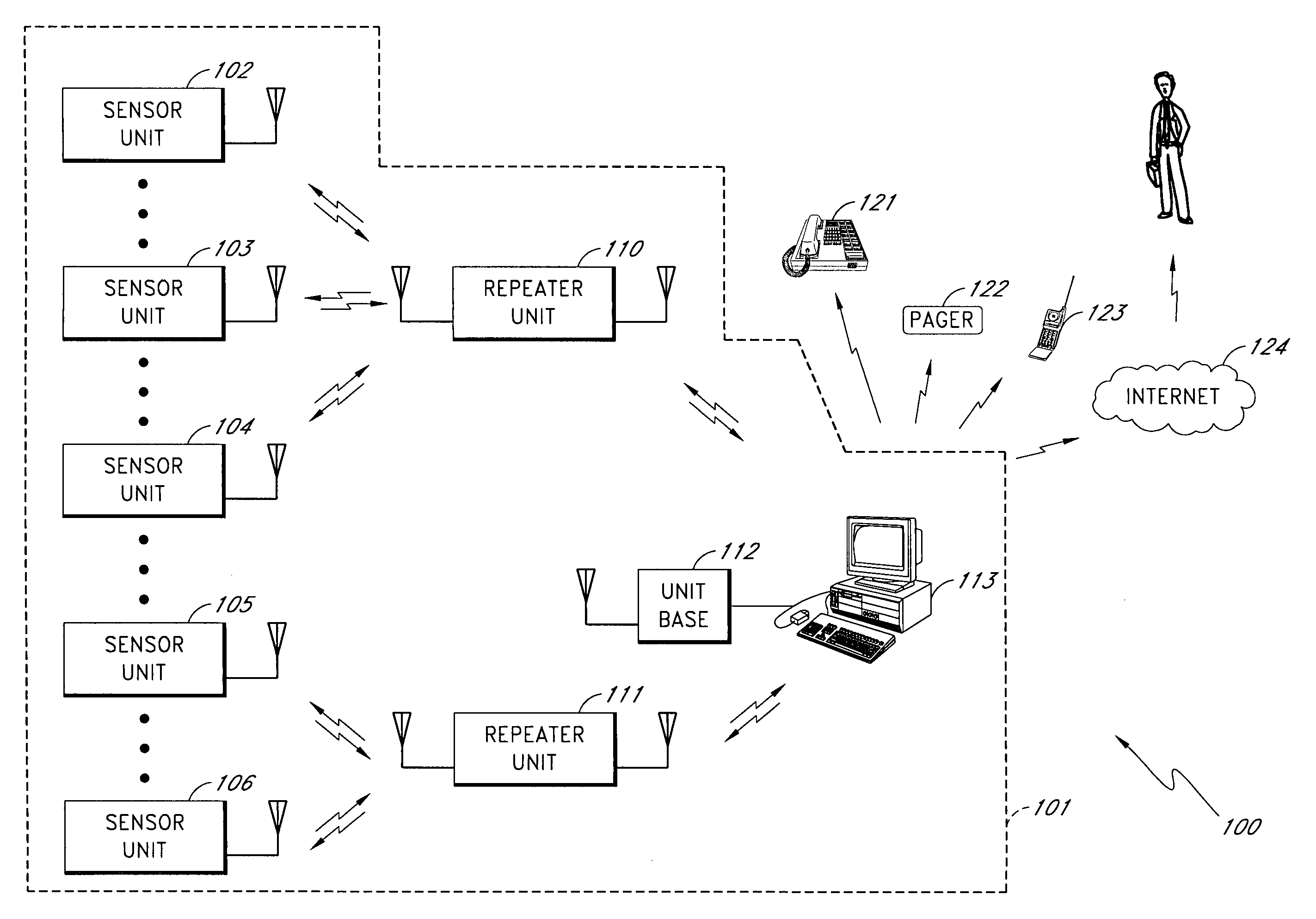
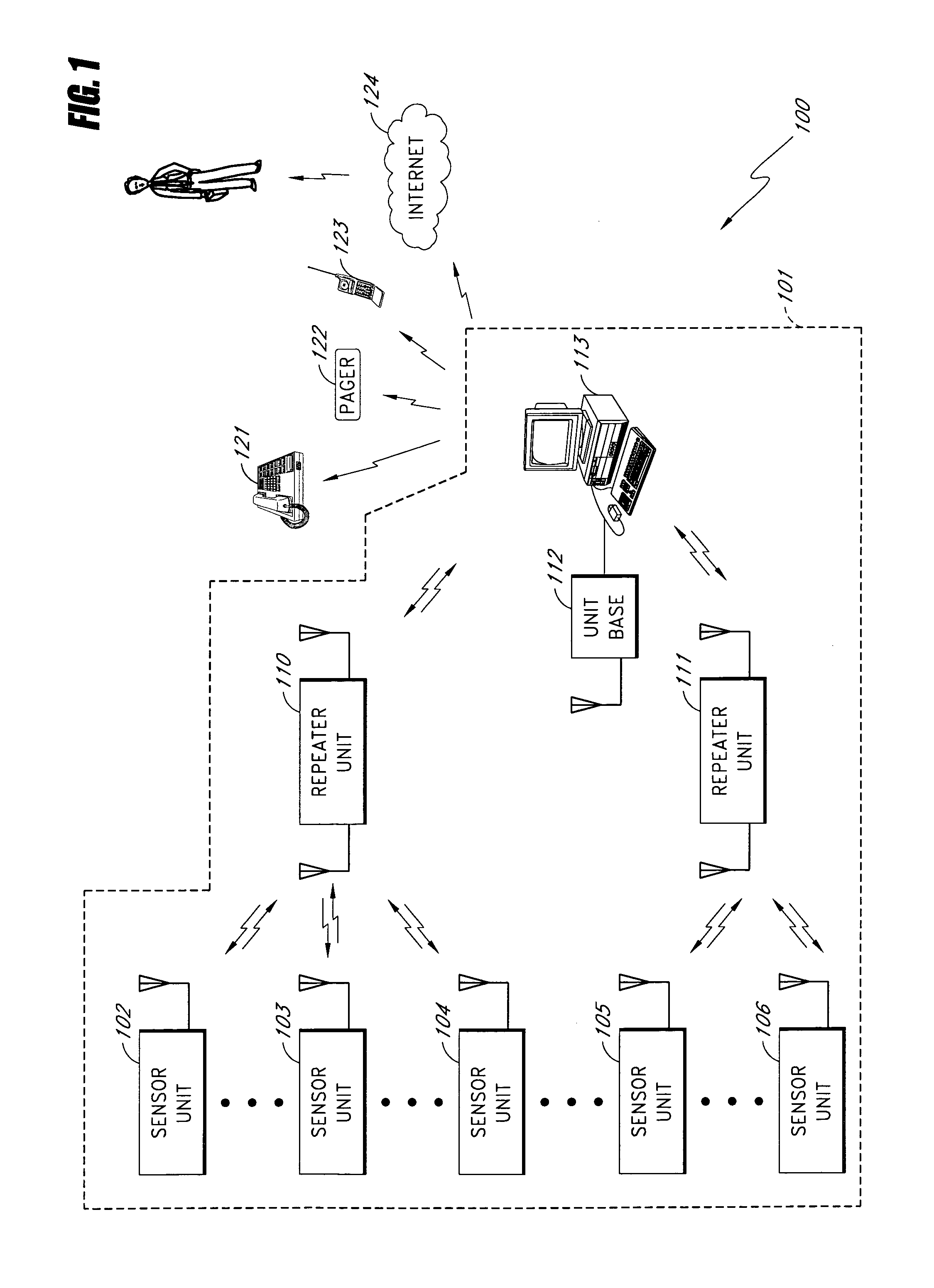
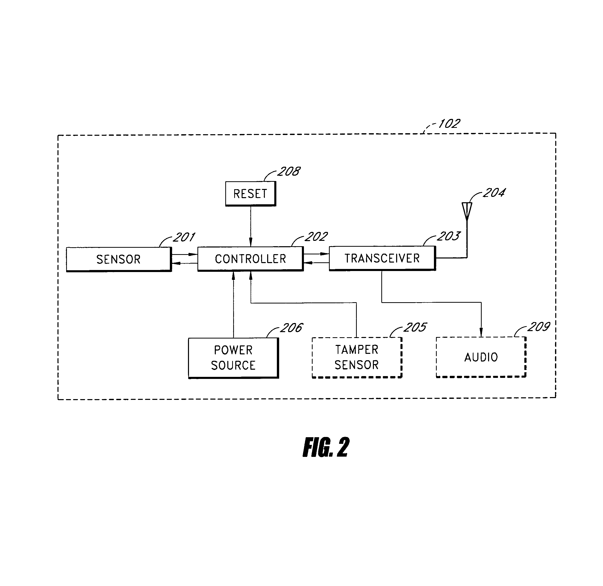
The present invention provides a wireless sensor system that is low-cost, robust, and can operate for an extended period of time without maintenance. The system includes sensor units placed throughout a building that detect abnormal conditions and communicate with a base unit. The sensor units measure various conditions and send the data to the base unit. The base unit can notify a responsible party of the abnormal condition and can also communicate with the sensor units. The sensor units are battery-operated and use spread-spectrum techniques for communication. The repeater unit acts as a relay between the sensor units and the base unit, and can also receive instructions from the central reporting station. The base unit includes a diskless PC that runs off of a read-only device and can send commands to the sensor units and receive data from them.

Problems solved by technology

Maintaining and protecting a building or complex is difficult and costly.
Some conditions, such as fires, gas leaks, etc. are a danger to the occupants and the structure.
Other malfunctions, such as water leaks in roofs, plumbing, etc. are not necessarily dangerous for the occupants, but can nevertheless cause considerable damage.
Sensors can be used to detect such adverse ambient conditions, but sensors present their own set of problems.
For example, adding sensors, such as, for example, smoke detectors, water sensors, and the like in an existing structure can be prohibitively expensive due to the cost of installing wiring between the remote sensors and a centralized monitoring device used to monitor the sensors.
Adding wiring to provide power to the sensors further increases the cost.
Moreover, with regard to fire sensors, most fire departments will not allow automatic notification of the fire department based on the data from a smoke detector alone.
Unfortunately, detecting fire by temperature rate-of-rise generally means that the fire is not detected until it is too late to prevent major damage.

Method used


Image

  • Wireless repeater for sensor system
  • Wireless repeater for sensor system
  • Wireless repeater for sensor system

Examples


Embodiment Construction

[0023]The entire contents of Applicant's co-pending application, application Ser. No. 10 / 856,390, titled “WIRELESS SENSOR SYSTEM,” filed May 27, 2004 is hereby incorporated by reference.

[0024]The entire contents of Applicant's co-pending application, application Ser. No. 10 / 856,231, titled “WIRELESS SENSOR UNIT,” filed May 27, 2004 is hereby incorporated by reference.

[0025]The entire contents of Applicant's co-pending application, application Ser. No. 10 / 856,170, titled “WIRELESS REPEATER FOR SENSOR SYSTEM,” filed May 27, 2004 is hereby incorporated by reference.

[0026]The entire contents of Applicant's co-pending application, application Ser. No. 10 / 856,387, titled “WIRELESS SENSOR MONITORING UNIT,” filed May 27, 2004 is hereby incorporated by reference.

[0027]The entire contents of Applicant's co-pending application, application Ser. No. 10 / 856,395, titled “METHOD AND APPARATUS FOR DETECTING CONDITIONS FAVORABLE FOR GROWTH OF FUNGUS,” filed May 27, 2004 is hereby incorporated by ref...


PUM


Abstract

A low cost, robust, repeater for a wireless ambient sensor system that provides an extended period of operability without maintenance is described. The repeater includes a controller and first and second transceivers. The controller is configured to control operation of said first transceiver and said second transceiver. The wireless repeater includes a repeater identification. The controller is configured to manage a sensor unit identification table that contains a list of sensor unit identification codes, where entries for the sensor unit identification table are received by the second transceiver from the base unit and identified by the repeater identification. The controller controls the first transceiver and the second transceiver to forward data from sensor units listed in said sensor unit identification table and to ignore data from sensor units not listed in said sensor unit identification table. The controller also controls the first transceiver and the second transceiver to forward data from the base unit that is addressed to sensor units listed in said sensor unit identification table and to ignore data from the base unit that is addressed to sensor units not listed in said sensor unit identification table. The controller places the first transceiver and the second transceiver in a low-power mode when no transmissions are expected from the base unit or from the sensor units listed in the sensor identification table.

Description

BACKGROUND OF THE INVENTION[0001]1. Field of the Invention[0002]The present invention relates to a wireless repeater for a sensor system providing bi-directional communication between a sensor (e.g., smoke sensor, fire sensor, temperature sensor, water, etc.) and a base unit in a building protection system.[0003]2. Description of the Related Art[0004]Maintaining and protecting a building or complex is difficult and costly. Some conditions, such as fires, gas leaks, etc. are a danger to the occupants and the structure. Other malfunctions, such as water leaks in roofs, plumbing, etc. are not necessarily dangerous for the occupants, but can nevertheless cause considerable damage. In many cases, an adverse ambient condition such as water leakage, fire, etc. is not detected in the early stages when the damage and / or danger is relatively small. Sensors can be used to detect such adverse ambient conditions, but sensors present their own set of problems. For example, adding sensors, such as...

Claims


Application Information

Patent Timeline
Patent Type & Authority Patents(United States)
IPC IPC(8): G08B1/08G08B25/00
CPCG08B25/009G08B1/08
Inventor KATES, LAWRENCE
Owner GOOGLE LLC
Learn More