
Solenoid actuated pneumatic valve with an integrated pass-through and a quick mount body

a technology of solenoid actuation and valve body, which is applied in the direction of valve housing, metal-working hand tools, couplings, etc., can solve the problems of affecting the performance of the valve assembly, the limitations and drawbacks of the conventional use of the conventional valve assembly, and the repetitive pneumatic driven operation in extremely large numbers, etc., to achieve the effect of overcoming the disadvantages and drawbacks, quick and easy removal or installation

Inactive Publication Date: 2006-05-02
MAC VALVES INC
View PDF17 Cites 0 Cited by
  • Summary
  • Abstract
  • Description
  • Claims
  • Application Information

AI Technical Summary

Benefits of technology

This solution significantly reduces downtime for maintenance by enabling quick and easy removal and replacement of the valve assembly, improving operational efficiency in high-speed manufacturing environments.

Problems solved by technology

Yet, as faster and smaller valves have evolved, certain limitations and drawbacks to the use of these conventional valve assemblies have become apparent.
Certain high-speed manufacturing and process environments perform repetitive pneumatically driven operations in extremely high numbers over a relatively short period of time.
All valve assemblies currently employed in the related art are subject to wear and durability limitations when used in rigorous environments that require high-speed, and high-repetition valve operation.
Wear and ultimate failure of these valve assemblies is expected.
When a failure occurs, the valve is removed and replaced.
It is also generally expected that these failures will cause production shut downs while the valve in question is replaced.
However, many applications run their processes 24 hours a day and scheduled maintenance periods are invasive to the process and time consuming.
In any event, the conventional solenoid operated valve assemblies require costly amounts of down-time to remove and replace.
Furthermore, the pressurized connections at their inlet, outlet, and pass-through require the use of known, conventional types of threaded fasteners that do not lend themselves to quick mounting or replacement.
This can lead to even longer down time during maintenance, especially where a number of valves in a given zone are involved.
Thus, removal and replacement times for conventional valves employed in these types of process systems is still excessive as it requires a number of hand tools and a moderate amount of physical manipulation to complete.

Method used


Image

  • Solenoid actuated pneumatic valve with an integrated pass-through and a quick mount body
  • Solenoid actuated pneumatic valve with an integrated pass-through and a quick mount body
  • Solenoid actuated pneumatic valve with an integrated pass-through and a quick mount body

Examples


Embodiment Construction

)

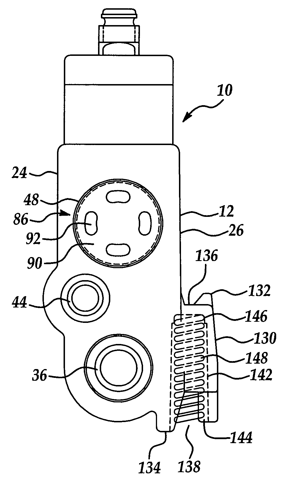
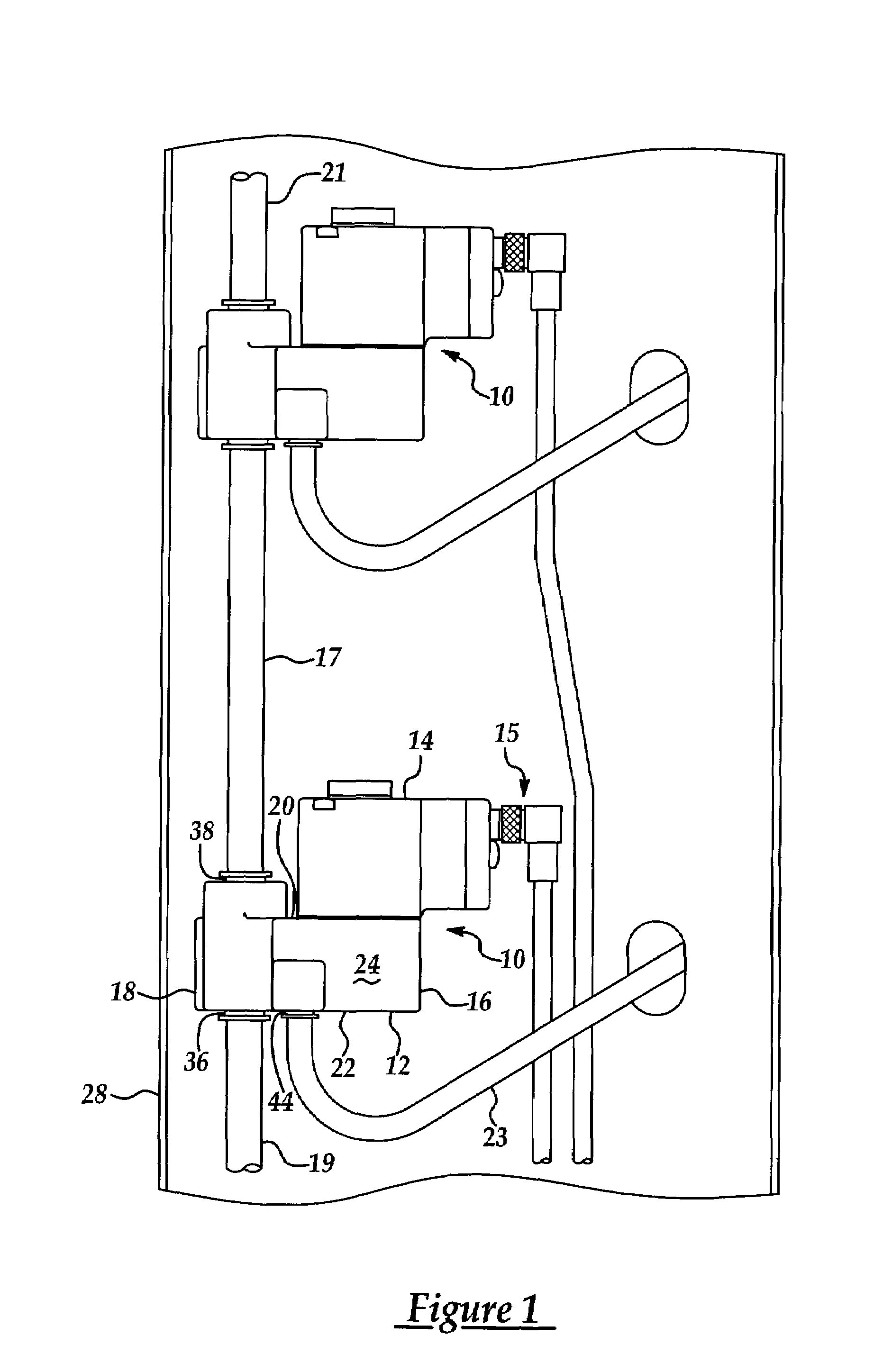
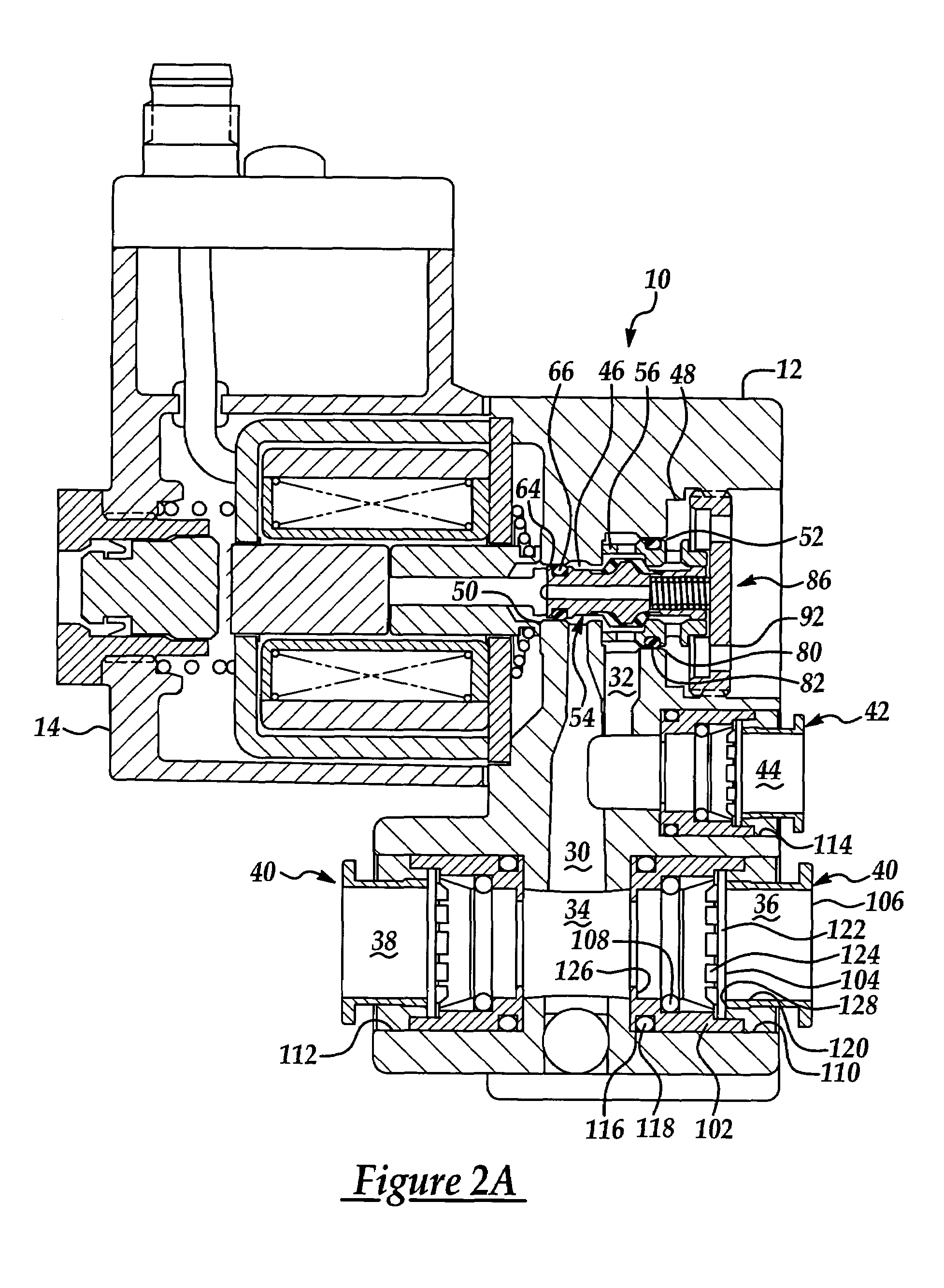
[0026]Referring now to the figures, where like numerals are used to designate like structure throughout the drawings, a pneumatic valve assembly of the present invention is generally indicated at 10 and 210. As shown in FIG. 1, two valve assemblies 10 of the present invention are pneumatically interconnected in series with a source of pressurized air. Each of the valve assemblies 10 includes a valve body 12 and an electromagnetic actuator assembly, such as a solenoid, generally indicated at 14 and mounted to the valve body 12. The valve body 12 has a thin rectangular shape defining top and bottom surfaces 16, 18, respectively, a pair of opposed side surfaces 20, 22 extending between the top and bottom surfaces 16 and 18 and end surfaces 24, 26. The actuator assembly 14 is mounted to the side surface 20 of the valve body 12. The actuator of the present invention may be of any known type typically used in pneumatic valves such as an electromagnetic solenoid having a floating armature...


PUM


Abstract

A solenoid actuated pneumatic valve assembly including a valve body having a pressurized air supply inlet port in fluid communication with a source of pressurized air, an outlet port adapted to be in fluid communication with at least one active pneumatically operated device, and a pass-through port. The pass-through port is adapted to be in fluid communication with and provide a pass-through of the supply of pressurized air to the inlet port of at least one other valve assembly such that the valves are mounted in series with respect to the supply of pressurized air. A latching assembly is also provided that is supported upon the valve body and is adapted to engage and be operatively retained within an aperture in a mounting plate.

Description

BACKGROUND OF THE INVENTION[0001]1. Field of the Invention[0002]The invention relates, generally, to solenoid actuated pneumatic valve assemblies and, more specifically, to a pneumatic valve having an integrated pass-through to allow the valve to be placed in series with other like valves and a quick mount body adapted to allow for rapid removal and replacement of the valve without fasteners.[0003]2. Description of the Related Art[0004]Pneumatic valve assemblies are well known in the art for controlling the flow of pressurized air to and from various pneumatically actuated devices such as linear actuators, rotary actuators, air outlets or any other pneumatic device or application requiring precise control of operating air. One common use of pneumatic valve assemblies includes using a series of individual valves to operate a conveyor system or to perform separate functional activities along a conveyor or an assembly line. In this manner, the individual valves are arranged along the m...

Claims


Application Information

Patent Timeline
Patent Type & Authority Patents(United States)
IPC IPC(8): F16L5/00F15B13/00F15B13/08F15B15/14F15B15/24F16K27/00F16K31/06
CPCF15B13/0817F15B13/0825F15B13/0857F16K31/0627F16K27/003Y10T403/602Y10T403/599Y10T24/44026Y10T137/86622Y10T137/6966F16K31/0603
Inventor WILLIAMS, KEVIN C.NEFF, ROBERT H.
Owner MAC VALVES INC
Learn More