
Fuel rail pulse damper with integral strengthening rib

a technology of pulse damper and fuel rail, which is applied in the direction of liquid fuel feeder, machine/engine, fuel injecting pump, etc., to achieve excellent wall flexure capability, excellent structural stability, and increase dynamic range and sensitivity

Inactive Publication Date: 2006-05-02
DELPHI TECH INC
View PDF13 Cites 8 Cited by
  • Summary
  • Abstract
  • Description
  • Claims
  • Application Information

AI Technical Summary

Benefits of technology

The improved damper achieves increased damping capacity with reduced stress levels, enhanced structural stability, and increased volume displacement, allowing for more effective absorption of pressure fluctuations without compromising the damper's fit within existing fuel rail configurations.

Problems solved by technology

Preferably, the short sides are somewhat higher than the comparable short sides of similar prior art dampers, to increase the captive air volume, yet are not high enough to preclude installation of the improved damper within an existing fuel rail configuration.

Method used


Image

  • Fuel rail pulse damper with integral strengthening rib
  • Fuel rail pulse damper with integral strengthening rib
  • Fuel rail pulse damper with integral strengthening rib

Examples


Embodiment Construction

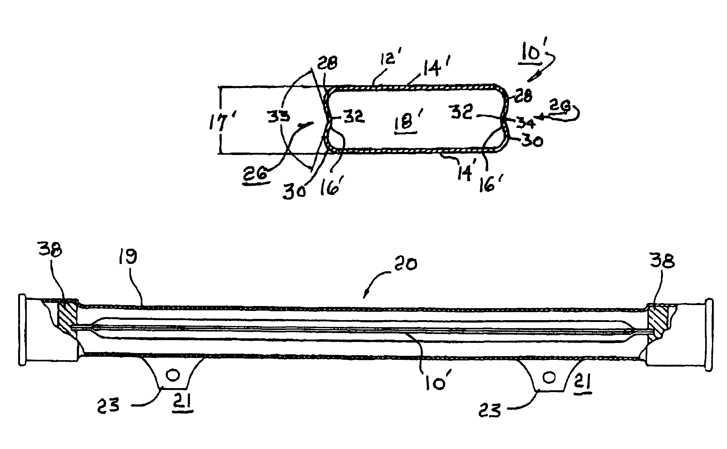
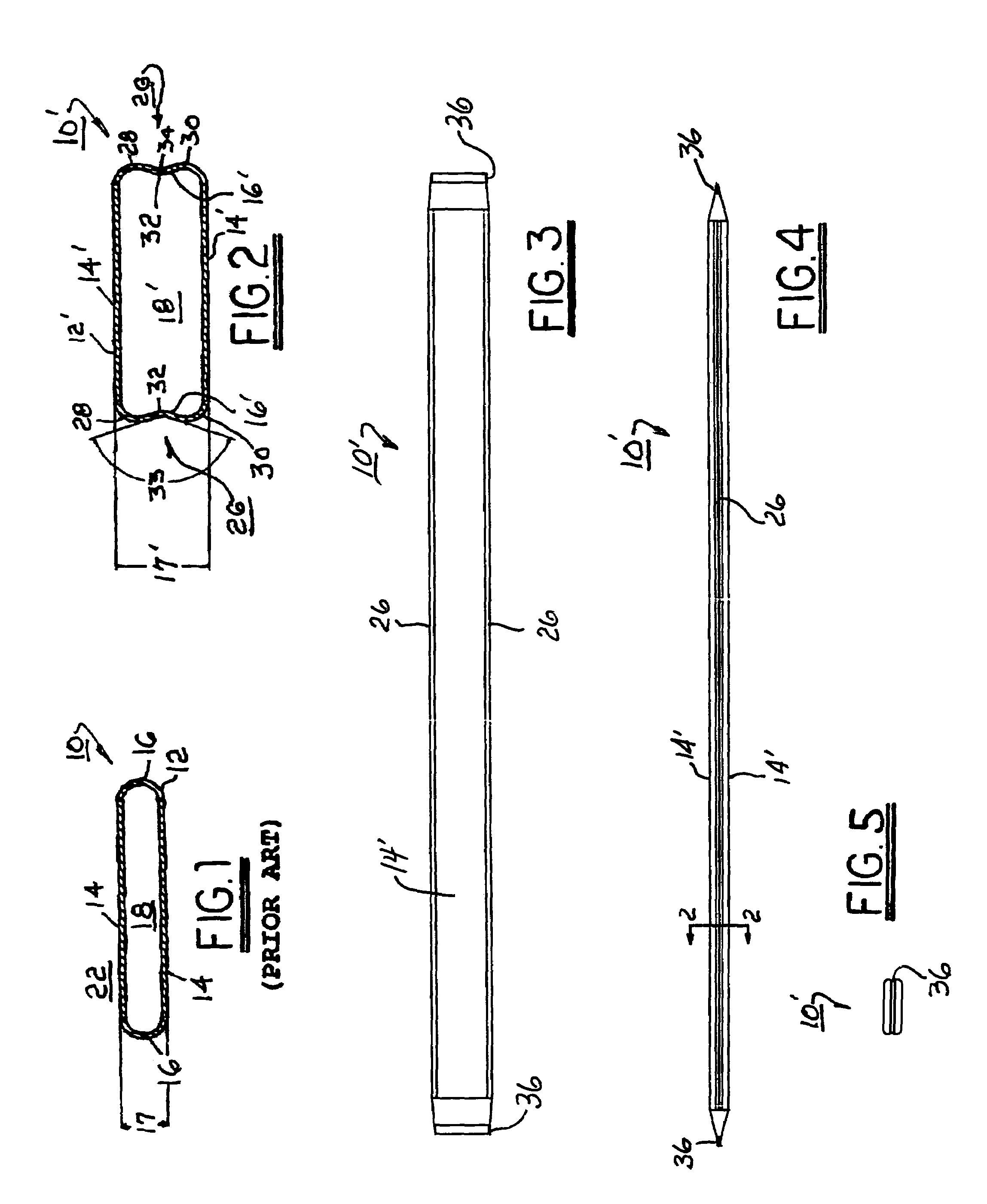
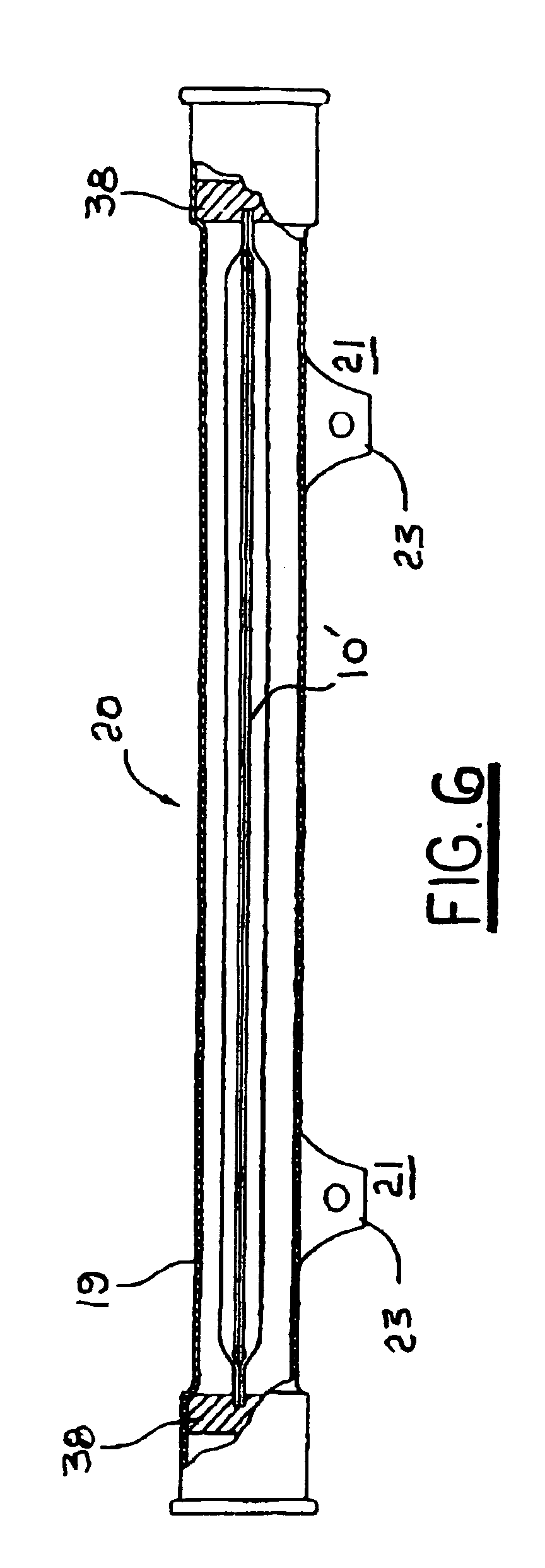
[0022]Referring to FIG. 1, a prior art internal pulsation damper 10 for inclusion within a fuel rail for an internal combustion engine is formed as an elongate pillow 12, FIG. 1 showing a transverse cross-sectional view thereof. Pillow 12 is formed of thin wall stainless steel having a wall thickness of about 0.012 inches, and is provided with first and second diaphragm sides 14 separated and connected by longitudinal rigid short sides 16 of height 17 (typically about 3.41 mm). The short sides are typically curved as shown such that the cross-sectional shape is referred to in the prior art as a “flat oval.” Sides 14 are joined (not shown) at the ends of pillow 12, as by compression of sides 16 (pinching) and welding of sides 14 together, to form a sealed chamber 18 within pillow 12. Chamber 18 is filled with a gas, preferably air. Pillow 12 is disposed within a fuel rail (not shown in FIG. 1 but similarly to improved pillow 12′ disposed in a fuel rail 20 as shown in FIG. 6). The asp...


PUM


Abstract

An internal pulse damper for a fuel rail. The damper has an increased captive air volume and consequent improved damping and stress characteristics. The improved damper is a pillow having a modified flat oval cross-sectional profile, with two long diaphragm sides and rigid short sides connecting the two long sides. At least one of the short sides, and preferably both, is strengthened by being provided with a longitudinal reverse bend or inwardly-extending longitudinal rib generally parallel with the long sides. Preferably, the short sides are somewhat higher than the comparable short sides of similar prior art dampers, to increase the captive air volume, yet are not high enough to preclude installation of the improved damper within an existing fuel rail configuration.

Description

TECHNICAL FIELD[0001]The present invention relates to fuel rails for internal combustion engines; more particularly, to devices for damping pulses in fuel being supplied to an engine via a fuel rail; and most particularly, to an improved fuel rail internal damper having increased damping capacity.BACKGROUND OF THE INVENTION[0002]Fuel rails for supplying fuel to fuel injectors of internal combustion engines are well known. A fuel rail is essentially an elongate fuel manifold connected at an inlet end to a fuel supply system and having a plurality of ports for mating with a plurality of fuel injectors to be supplied.[0003]Fuel rail systems may be recirculating, as is commonly employed in diesel engines wherein fuel sedimentation and injector clogging can be a problem. In gasoline-powered engines, fuel rails are more typically “returnless” or dead ended, wherein all fuel supplied to the fuel rail is dispensed by the fuel injectors.[0004]A well-known problem in fuel rail systems, and es...

Claims


Application Information

Patent Timeline
Patent Type & Authority Patents(United States)
IPC IPC(8): F02M55/04F02M37/00F02M63/00F02M69/46
CPCF02M69/465F02M55/04F02M37/0041F02M2200/315
Inventor BRAUN, CHARLES W.BECENE, AHMET T.
Owner DELPHI TECH INC
Learn More