
Engine operated machine system

a technology of engine and machine body, which is applied in the direction of machines/engines, mechanical devices, cylinders, etc., can solve the problems of general obligation of vibration insulators, and achieve the effect of avoiding complication and increasing the weight of the structur

Active Publication Date: 2006-05-02
HONDA MOTOR CO LTD
View PDF4 Cites 2 Cited by
  • Summary
  • Abstract
  • Description
  • Claims
  • Application Information

AI Technical Summary

Benefits of technology

[0007]Accordingly, it is an object of the present invention to provide an engine operated machine system including a vibration insulator disposed between a center of gravity of and a center of vibration of an engine, wherein the center of vibration of the engine is made closer to the position of the vibration insulator by mounting an auxiliary weight to a crankshaft, thereby minimizing the application of the vibration from the engine to a support rod.
[0009]With the first feature, it is possible to bring the center of vibration ultimately close to the position of the vibration insulator by selecting the weight and position of the auxiliary weight, and to enhance the vibration-absorbing effect of the vibration insulator to reduce the application of the vibration to the support rod, thereby alleviating the discomfort provided to an operator.
[0011]With the second feature, the centrifugal forces produced by the auxiliary weight and the counterweight are balanced with each other, and hence it is possible to prevent the generation of an extra rotational vibration due to the provision of the weights.
[0013]With the third feature, the pair of oil slingers also serve as the auxiliary weight and the counterweight, and hence it is unnecessary to mount a special weight, so that it is possible to avoid the complication and an increase in weight of the structure.

Problems solved by technology

In many cases, however, the vibration insulator is generally obliged to be disposed between the center of gravity of and the center of vibration of the engine because of the limitation in the structure.

Method used


Image

  • Engine operated machine system
  • Engine operated machine system
  • Engine operated machine system

Examples


Embodiment Construction

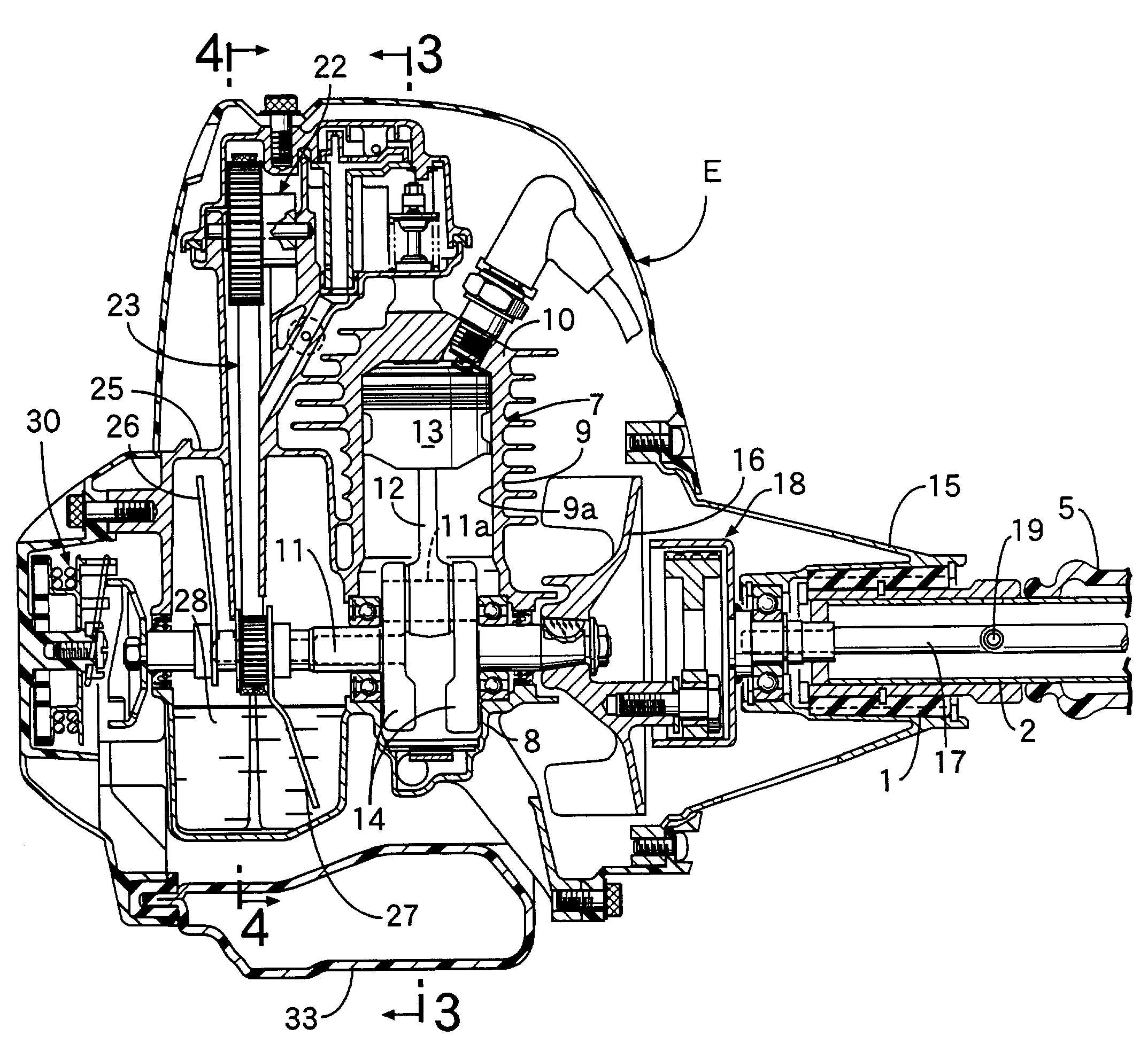
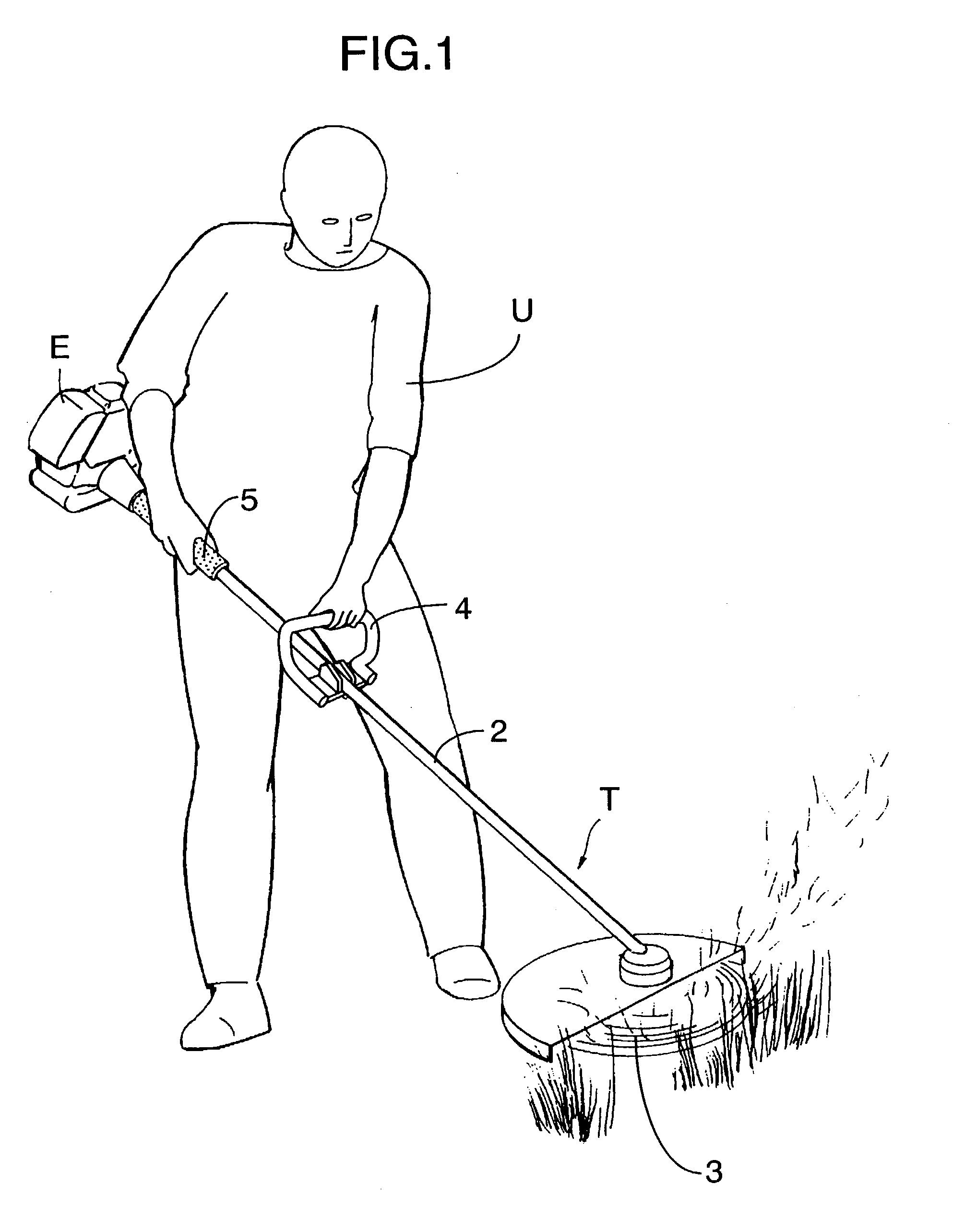
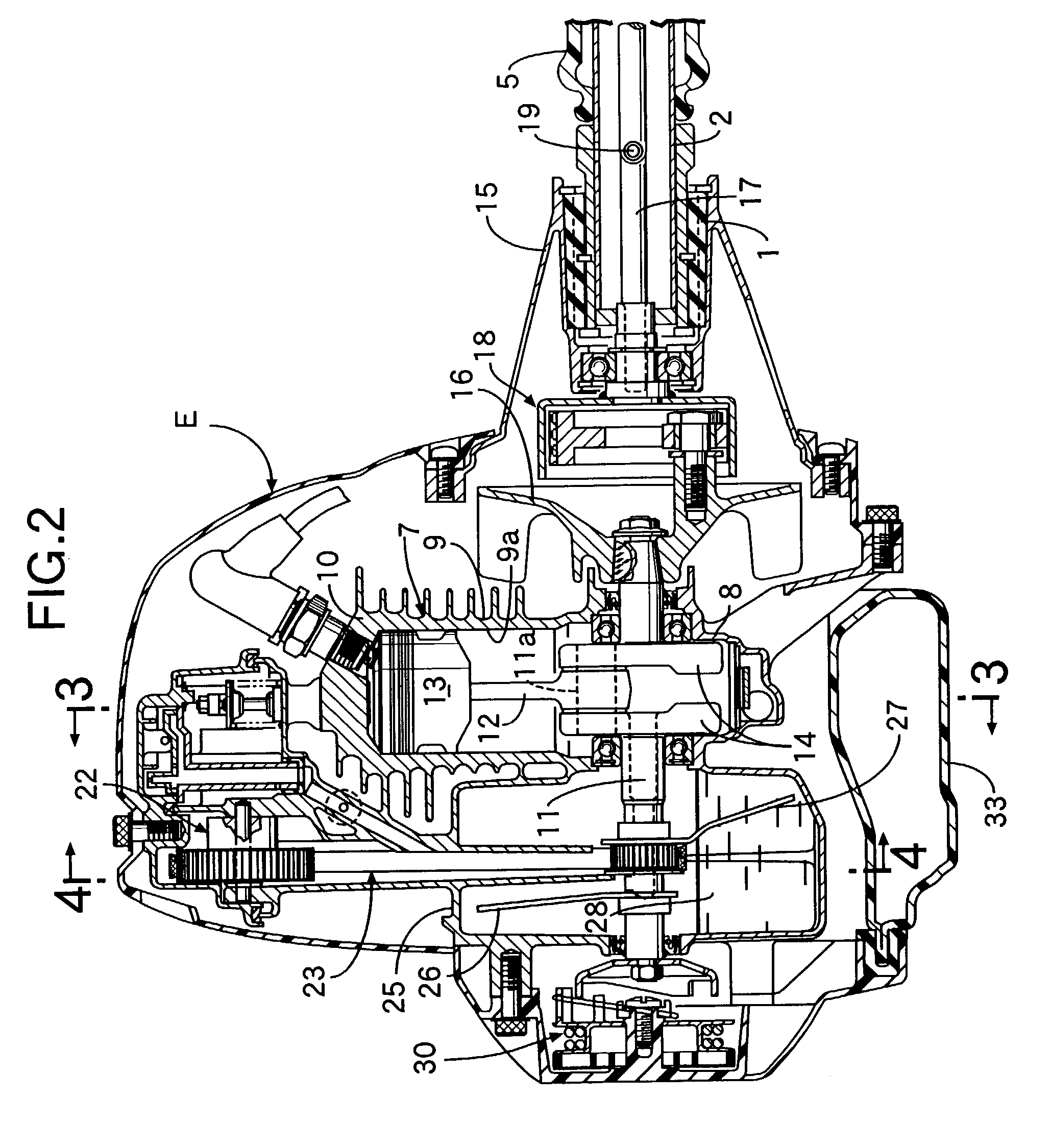
[0020]Referring first to FIGS. 1 and 2, a power trimmer T as an engine operated machine system includes a 4-cycle and single-cylinder engine E, a hollow support rod 2 connected at its rear end to a stationary structure of the engine E through a vibration insulator 1, and a cutting blade 3 as a working instrument rotatably supported at a front end of the support rod 2. A handle 4 and a grip 5 to be grasped by an operator U are mounted in a longitudinal arrangement on the support rod 2. A throttle lever (not shown) for controlling a throttle valve of the engine E is mounted in the vicinity of the grip 5.

[0021]As shown in FIGS. 2 to 4, the engine E includes a crankcase 8, an engine body 7 including a cylinder block 9 and a cylinder head 10, a crankshaft 11 supported in the crankcase 8, and a piston 13 connected to a crankpin 11a of the crankshaft 11 through a connecting rod 12 and adapted to reciprocally move within a cylinder bore 9a in the cylinder block 9.

[0022]A balance weight 14 i...


PUM


Abstract

In an engine operated machine system including a hollow support rod connected at one end to an engine through a vibration insulator, an auxiliary weight is mounted at the other end of a crankshaft for generating a centrifugal force in the same direction as an inertia force of a piston, when the piston reaches top and bottom dead centers. Thus, it is possible to bring a center of gravity of the engine closer to the position of the vibration insulator, thereby suppressing the application of the vibration from the engine to the support rod to the utmost.

Description

BACKGROUND OF THE INVENTION[0001]1. Field of the Invention[0002]The present invention relates to an engine operated machine system including an engine, a hollow support rod connected at one end to the engine through a vibration insulator, a working instrument supported at the other end of the support rod, a drive shaft disposed within the support rod and connected coaxially to one end of a crankshaft of the engine to drive the working instrument, and a pair of lubrication oil-scattering oil slingers protruding diametrically and secured to the other end of the crankshaft, the vibration insulator being disposed between a center of gravity of the engine and a center of vibration of the engine, and particularly to an engine operated machine system improved so that the support rod is prevented to the utmost from being vibrated by the vibration of the engine.[0003]2. Description of the Related Art[0004]A conventional engine operated machine system is widely used as a power trimmer (for ex...

Claims


Application Information

Patent Timeline
IPC IPC(8): F02B75/06F02B63/00F02B77/00F02B63/02F02B75/02F02B75/16F02F1/00F16F15/26F16F15/28F16N7/26
CPCF01L1/024F02B63/02F02B75/16F02F1/002F16F15/283Y10T74/2184F02B2275/20F02B2075/027
Inventor MOMOSAKI, TAMOTSUTABATA, YUTAKAITO, KEITANASUNO, TOSHIHARU
Owner HONDA MOTOR CO LTD
Learn More