
Lowering of refrigerant emissions by cycling of a variable displacement compressor

a variable-diameter compressor and refrigerant technology, applied in the field of air conditioning systems, can solve the problems of high refrigerant emission rates, and achieve the effect of limiting refrigerant emission

Active Publication Date: 2006-05-02
MAHLE INT GMBH
View PDF7 Cites 5 Cited by
  • Summary
  • Abstract
  • Description
  • Claims
  • Application Information

AI Technical Summary

Benefits of technology

The invention is an air conditioning system for vehicles that reduces refrigerant emissions. It achieves this by using a variable compressor that engages in a controlled manner based on engine operation and air conditioning needs. The system includes a compressor, condenser, evaporator, and suction fluid line, among others. An accumulator / dehydrator is also included in the suction fluid line for accumulating refrigerant. The invention also includes various valves for controlling the flow of refrigerant through the system. The technical effect of the invention is to reduce refrigerant emissions and enhance the efficiency of air conditioning systems in vehicles.

Problems solved by technology

Consequently, the absence of refrigerant oil may also result in high rates of refrigerant emission.

Method used


Image

  • Lowering of refrigerant emissions by cycling of a variable displacement compressor
  • Lowering of refrigerant emissions by cycling of a variable displacement compressor
  • Lowering of refrigerant emissions by cycling of a variable displacement compressor

Examples


Embodiment Construction

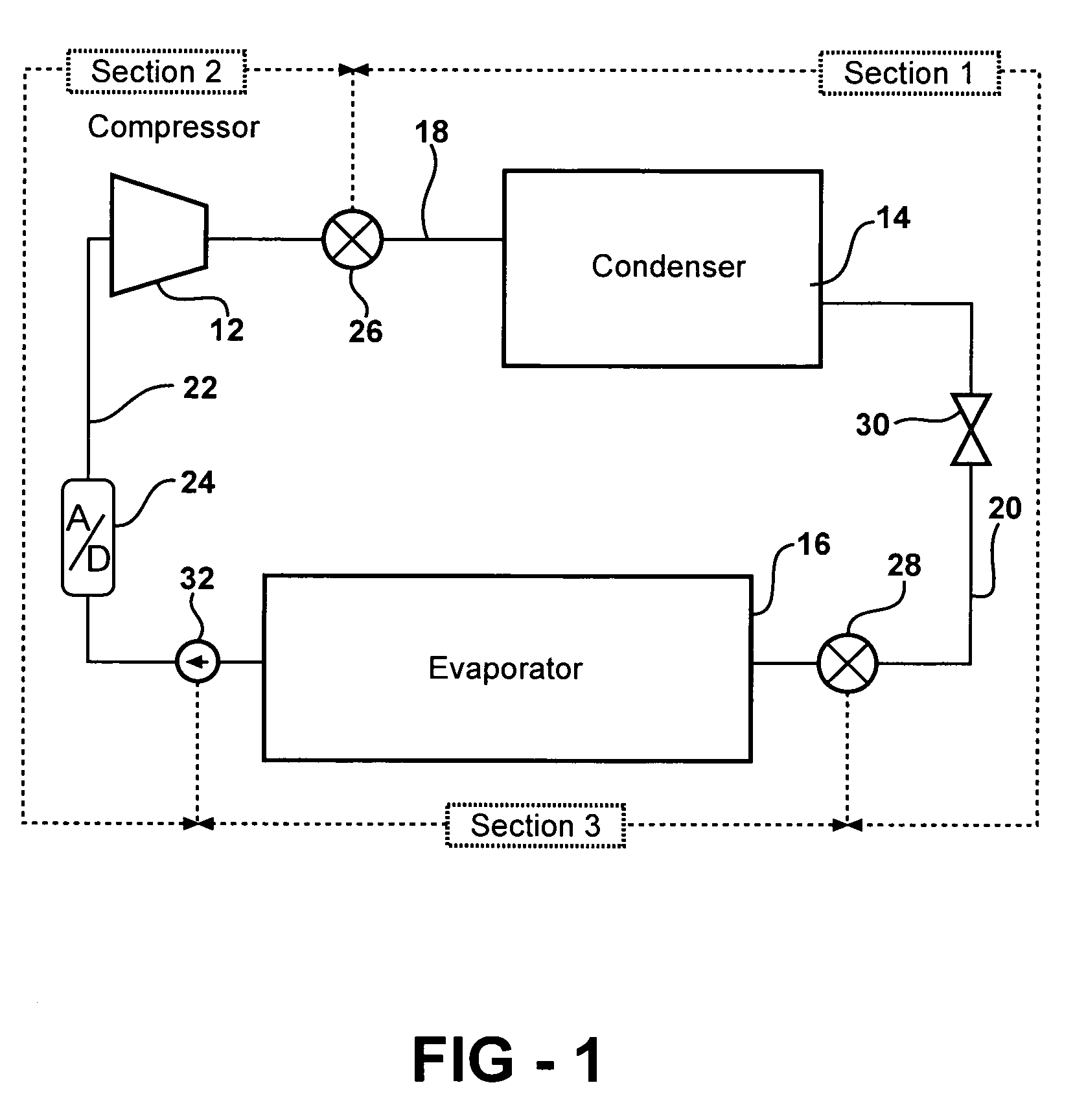
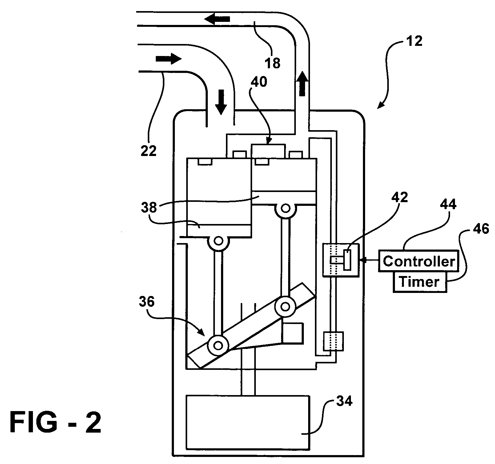
[0018]As alluded to above, the subject invention relates to an air conditioning system for a vehicle that comprises a compressor 12 for compressing a refrigerant, a condenser 14 for condensing the refrigerant, and an evaporator 16 for evaporating the refrigerant. Of course, a discharge fluid line 18 interconnects the compressor 12 and the condenser 14, while a liquid fluid line 20 interconnects the condenser 14 and the evaporator 16, and a suction fluid line 22 interconnects the evaporator 16 and the compressor 12 (it being appreciated that FIG. 1 is not proportional as it is schematic).

[0019]As is well known in the art, an accumulator / dehydrator (A / D) 24 is disposed in the suction fluid line 22 for accumulating refrigerant.

[0020]In addition, various valves 26, 28 and 32 are included for controlling the flow of refrigerant through the system. A thermal expansion device 30 is also disposed in the liquid fluid line 20 between the condenser 14 and the evaporator 16. The expansion devic...


PUM


Abstract

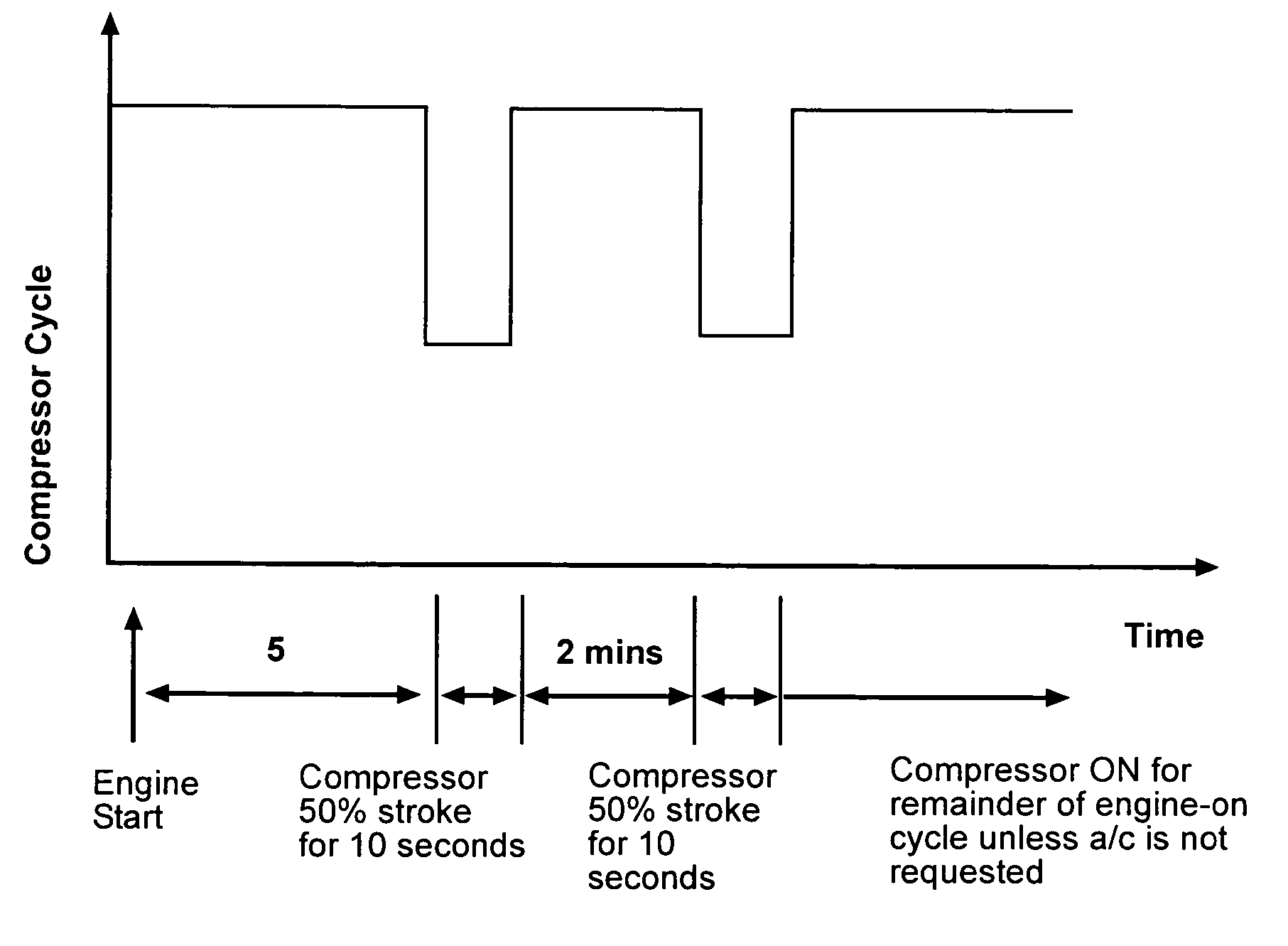
In order to reduce refrigerant leakage from an automotive air conditioning system, the leakage paths are kept sealed by automatically reducing the output of a variable displacement compressor (12) after initial operation of the engine for a predetermined number of five minutes, and then only for a predetermined number of ten seconds, that is, so long as there has been an air conditioning on signal by the operator. After the reduction in output for ten seconds, the output of the compressor (12) is returned to full output for a predetermined number of two air-conditioning minutes, which is then followed by another ten seconds of reduced output.

Description

CROSS REFERENCE TO RELATED APPLICATION[0001]This application claims the benefit of provisional application Ser. No. 60 / 520,743 filed Nov. 17, 2003.BACKGROUND OF THE INVENTION[0002]1. Field of the Invention[0003]The subject invention relates to an air conditioning system for a vehicle, frequently referred to as a heating, ventilating and air conditioning (HVAC) system.[0004]2. Description of the Prior Art[0005]Such systems typically include a compressor for compressing a refrigerant, a condenser for condensing the refrigerant, an evaporator for evaporating the refrigerant, a discharge fluid line interconnecting the compressor and the condenser, a liquid fluid line interconnecting the evaporator and the condenser, and a suction fluid line interconnecting the evaporator and the compressor. Also, such systems utilize various valve arrangements for controlling flow through the system during operation and during shutdown and / or in response to a leak of refrigerant in the system. In additi...

Claims


Application Information

Patent Timeline
Patent Type & Authority Patents(United States)
IPC IPC(8): B60H1/32F25B31/00F25B49/02
CPCB60H1/3225F25B49/022B60H2001/3238B60H2001/3272F25B2500/221F25B2327/001F25B2400/076
Inventor AHMED, S. UMAIRWOLFE, IV, EDWARD I.KADLE, PRASAD S.KUMPF, WILLIAM J.
Owner MAHLE INT GMBH
Learn More