Lens barrel

a barrel and lens technology, applied in the field of lenses barrels, can solve the problems of large size, complicated drive mechanism of the rotatable ring, difficult to make the stop device work properly, etc., and achieve the effect of simple structur

Inactive Publication Date: 2006-04-18
ASAHI KOGAKU KOGYO KK
View PDF136 Cites 23 Cited by
  • Summary
  • Abstract
  • Description
  • Claims
  • Application Information

AI Technical Summary

Benefits of technology

[0005]The present invention provides a lens barrel including the above-described type of rotatable ring, which performs the advancing / retracting operation and the fixed-position rotating operation in different states, wherein a limit for the rotational movement of the rotatable ring can be properly determined with a simple structure.
[0006]According to an aspect of the present invention, a lens barrel is provided, including at least one optical element configured to be guided along an optical axis; a rotatable ring rotatable about a rotational axis extending in a direction of the optical axis, the optical element rotating along the optical axis by a rotation of the rotatable ring; an outer annular member, which is non-rotatable about the rotational axis, supporting the rotatable ring inside the outer annular member, and including at least one circumferential groove located on an inner peripheral surface of the outer annular member which faces the rotatable ring; an advancing / retracting mechanism, provided between an outer peripheral surface of the rotatable ring and the inner peripheral surface of the outer annular member, configured to move the rotatable ring along the optical axis between front and rear limits for movement of the rotatable ring in the optical axis direction relative to the outer annular member when the rotatable ring is rotated; at least one rotational projection located on the outer peripheral surface of the rotatable ring, wherein the at least one rotational projection is engaged in the at least one circumferential groove such that the rotatable ring is rotatable at an axial fixed position without moving along the optical axis when the rotatable ring is moved to one of the front and rear limits by the advancing / retracting mechanism; and a stopper insertable into and removable from the at least one circumferential groove at an intermediate point between opposite ends of the at least one circumferential groove. The stopper limits the range of rotation of the rotatable ring about the rotational axis relative to the outer annular member by engaging the rotational projection in a state where the stopper is positioned in the circumferential groove. The stopper stops preventing the range of rotation of the rotatable ring in a state where the stopper is positioned outside the circumferential groove.
[0018]In another embodiment of the present invention, a lens barrel is provided, including at least one optical element configured to be guided along an optical axis; a pair of rotatable rings rotatable about a rotational axis extending in a direction of the optical axis, the optical element rotating along the optical axis by a rotation of the pair of rotatable rings; an outer annular member which is non-rotatable about the rotational axis, supporting the pair of rotatable rings inside the outer annular member, and including at least one circumferential groove located on an inner peripheral surface of the outer annular member which faces the pair of rotatable rings; an advancing / retracting mechanism, provided between an outer peripheral surface of the pair of rotatable rings and the inner peripheral surface of the outer annular member, for moving the pair of rotatable rings along the optical axis between front and rear limits for movement of the pair of rotatable rings in the optical axis direction relative to the outer annular member when the pair of rotatable rings is rotated; at least one rotational projection located on an outer peripheral surface of one of the pair of rotatable rings, wherein the at least one rotational projection is engaged in the at least one circumferential groove such that the pair of rotatable rings is rotatable at an axial fixed position without moving along the optical axis when the pair of rotatable rings is moved to one of the front and rear limits by the advancing / retracting mechanism; at least one engaging projection located on an outer peripheral surface of the other of the pair of rotatable rings to be engaged in the at least one circumferential groove, together with the at least one rotational projection, in a state where the pair of rotatable rings and the outer annular member are positioned relative to each other in the optical axis direction such that the at least one rotational projection is engaged in the at least one circumferential groove; at least one insertion / removable hole located on the outer annular member such that the at least one engaging projection can be inserted and removed into and from the at least one circumferential groove through the insertion / removable hole when the at least one rotational projection of the pair of rotatable rings rotates to an assembling / disassembling angular position on the outer annular member in a direction of rotation thereof; and a stopper insertable and removable into and from the at least one circumferential groove at an intermediate point between opposite ends of the at least one circumferential groove. The stopper is engageable with the at least one rotational projection to prevent the at least one rotational projection of the pair of rotatable rings from rotating to the assembling / disassembling angular position in a state where the stopper is in the at least one circumferential groove. The stopper stops preventing the at least one rotational projection of the pair of rotatable rings from rotating to the assembling / disassembling angular position in a state where the stopper is positioned outside the circumferential groove.

Problems solved by technology

In such known retractable photographing lenses, a drive mechanism for driving the rotatable ring is generally complicated and large in size.
However, in the case where the rotatable ring is a type which performs an advancing / retracting operation in which the rotatable ring rotates while advancing or retracting along the optical axis, and a fixed-position rotating operation in which the rotatable ring rotates at a predetermined axial fixed position without moving along the optical axis, the structure of the stop device is generally complicated; moreover, it is generally difficult to make the stop device operate properly.

Method used


Image

  • Lens barrel
  • Lens barrel
  • Lens barrel

Examples


Embodiment Construction

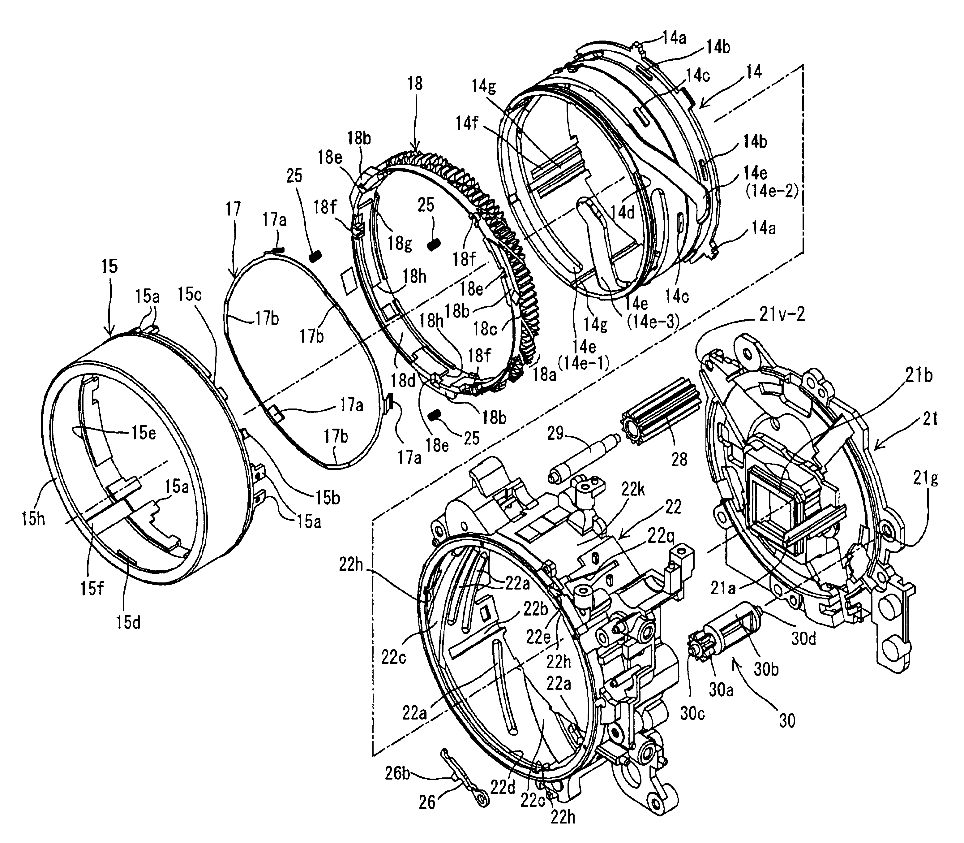
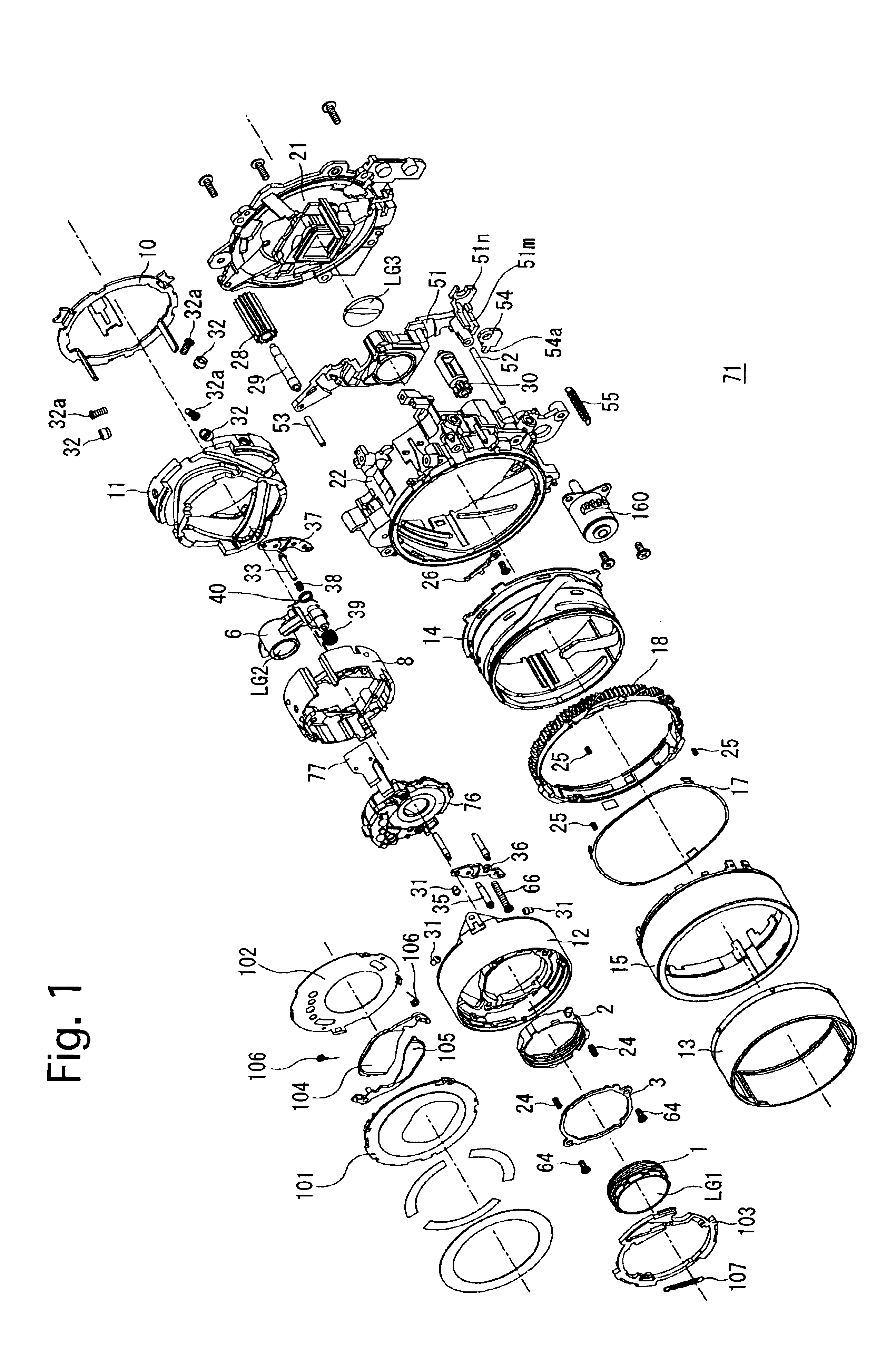
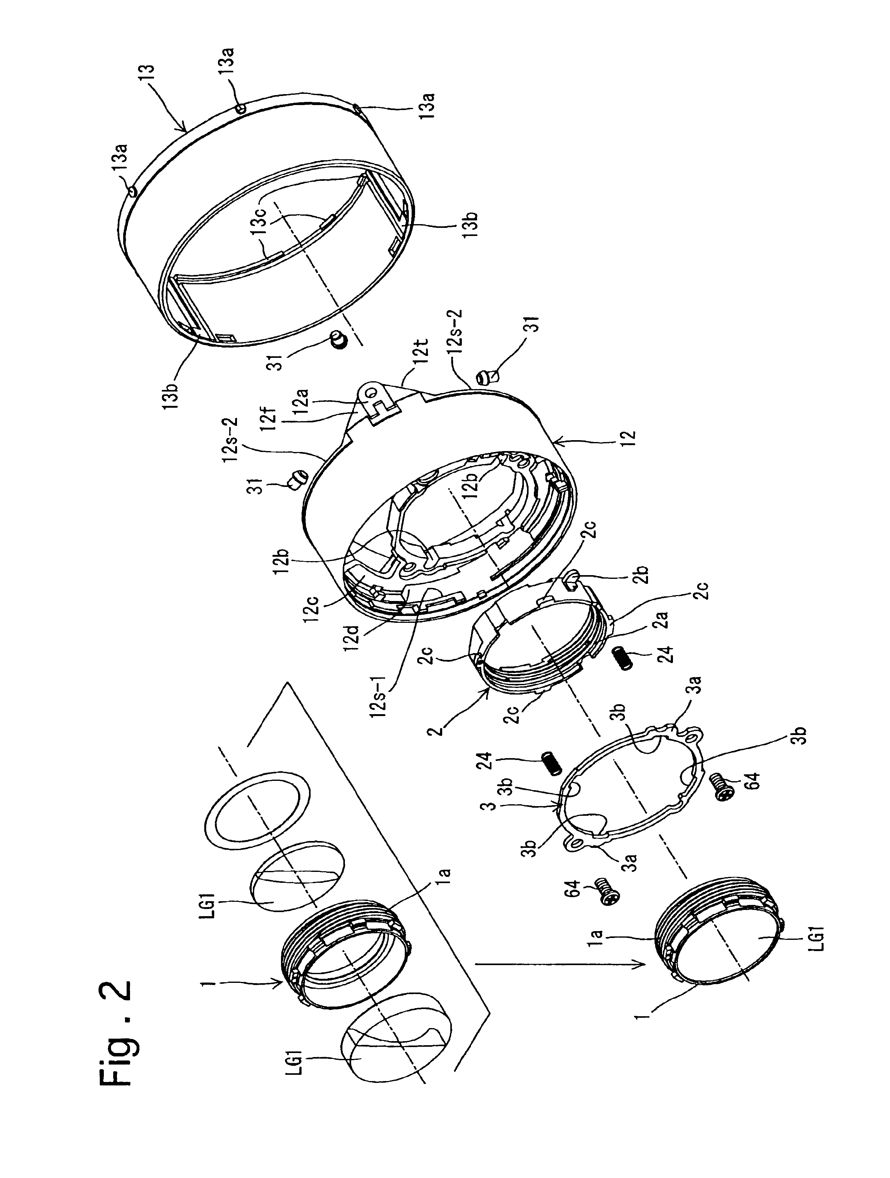
[0182]In some of the drawings, lines of different thicknesses and / or different types of lines are used as the outlines of different elements for the purpose of illustration. Additionally, in some cross sectional drawings, several elements are shown on a common plane, though positioned in different circumferential positions, for the purpose of illustration.

[0183]In FIG. 22, the symbols “(S)”, “(L)”, “(R)” and “(RL)” which are each appended as a suffix to the reference numeral of some elements of a present embodiment of a zoom lens (zoom lens barrel) 71 (see FIGS. 5 through 10) indicate that the element is stationary, the element is solely movable linearly along a lens barrel axis Z0 (see FIGS. 9 and 10) without rotating about the lens barrel axis Z0, the element is rotatable about the lens barrel axis Z0 without moving along the lens barrel axis Z0, and the element is solely movable along the lens barrel axis Z0 while rotating about the lens barrel axis Z0, respectively. Additionally...


PUM


Abstract

A lens barrel includes a rotatable ring, a non-rotatable outer annular member having a circumferential groove located on the inner peripheral surface thereof, an advancing / retracting mechanism configured to move the rotatable ring along the optical axis between movement limits of the rotatable ring, a rotational projection located on the outer peripheral surface of the rotatable ring such that the projection is engaged in the circumferential groove when the rotatable ring is moved to one of the movement limits, and a stopper which is insertable into and removable from the circumferential groove at an intermediate point between opposite ends of the groove. The stopper limits the range of rotation of the rotatable ring relative to the outer annular member by engaging the rotational projection in a state where the stopper is positioned in the circumferential groove, and the stopper stops preventing the range of rotation of the rotatable ring in a state where the stopper is positioned outside the circumferential groove.

Description

BACKGROUND OF THE INVENTION[0001]1. Field of the Invention[0002]The present invention relates to a lens barrel such as a photographing (imaging) lens which incorporates a rotatable ring performing an advancing / retracting operation in which the rotatable ring moves along an optical axis while rotating, and a fixed-position rotating operation in which the rotatable ring rotates at an axial fixed position without moving along the optical axis.[0003]2. Description of the Related Art[0004]Retractable photographing lenses in which a rotatable ring such as a cam ring advances along an optical axis while rotating from a fully retracted position toward a ready-to-photograph position (e.g., zooming range of zoom lens) upon power being turned ON and in which the cam ring stops advancing upon reaching the ready-to-photograph position to be rotatable at an axial fixed position on the optical axis without rotating are known in the art. In such known retractable photographing lenses, a drive mecha...

Claims


Application Information

Patent Timeline
Patent Type & Authority Patents(United States)
IPC IPC(8): G03B17/00G02B7/00G02B7/02G02B7/08G02B7/10G02B15/14
CPCG02B7/022G02B7/026G02B15/14G02B7/102G02B7/08G02B15/143G02B7/04G03B2217/00
Inventor NOMURA, HIROSHI
Owner ASAHI KOGAKU KOGYO KK
Why Eureka
Try Eureka