
Method for displaying position of an aircraft in a display for air traffic control

a technology of air traffic control and aircraft position, which is applied in the direction of navigation instruments, using reradiation, instruments, etc., can solve the problems of inability to comprehensively and visually grasp the relative relationships of positions, velocities and travel directions of plural aircraft at air traffic control consoles, and often by midair collisions of aircraft, so as to ensure the safety distance between aircraft and effectively avoid the occurrence of near collisions

Inactive Publication Date: 2006-04-18
REALVIZ +1
View PDF15 Cites 44 Cited by
  • Summary
  • Abstract
  • Description
  • Claims
  • Application Information

AI Technical Summary

Benefits of technology

Enables comprehensive and visual monitoring of aircraft relationships, allowing for timely prediction and prevention of near misses or collisions by ensuring safety distances and alerting controllers with intuitive and dynamic display cues.

Problems solved by technology

Tragic accidents by midair collision of aircraft have frequently occurred everywhere in the world.
When multiple aircraft exist in an air traffic control area, there is a possibility that he or she incorrectly images the flight status since he or she bears a heavy burden.
There is a possibility that his or her incorrect image causes near miss or midair collision.
However, it is impossible to comprehensively and visually grasp relative relationships such as the positions, the velocities and the travel directions of plural aircrafts at an air traffic control console with this technique.(2) A system wherein the flight trajectory of aircraft is displayed in a three-dimensional reduced model space of an area surrounding an airport on a display screen based on aircraft position data detected by a radar system in air traffic control is disclosed in JP-A-8-110380.
However, in this technique, although it is possible to display the flight trajectories and the current positions of respective aircraft to a certain terrain, it is impossible to display relative relationships, such as the velocities, the travel directions, the inter-distance and the changing statuses of the respective aircrafts.(3) JP-A-9-304526 discloses a technique wherein in order to visually recognize the positions, the velocities, the travel directions, the attitudes and the like of aircraft, a plane containing a reference point on a runway extending in substantially parallel with the ground surface is displayed as a reference plane apparently in three dimensions on a display screen, and the aircraft marks indicating of the respective aircrafts, the projection marks of the respective aircrafts projected onto the reference plane, the altitude vectors indicating the altitudes of the respective aircraft, the velocity vectors indicating the velocities of the respective aircraft and the trail vectors indicating the flight trajectories of the respective aircrafts are displayed apparently in three dimensions in a method for displaying air traffic control information.
Although it is possible to grasp the positions, the altitudes, the velocities, the travel directions and the flight trajectories of the respective aircraft apparently in three dimensions with this technique, it is difficult to accurately and visually grasp relative relationships between the respective aircraft, in particular the distance and the changing status between the respective aircraft.
It is impossible to visually grasp which one of neighboring aircraft a controller should pay more attention to and how much attention he or she should pay if caution is needed.
As explained, with the conventional techniques, it is difficult to predict the possibility of near miss or collision between aircraft in order to avoid the occurrence of the near miss or collision by comprehensively and visually grasping relative relationships between flying aircrafts including the distance between aircraft, the changing status in the distance between aircraft, and the travel directions of the respective aircraft.

Method used


Image

  • Method for displaying position of an aircraft in a display for air traffic control
  • Method for displaying position of an aircraft in a display for air traffic control
  • Method for displaying position of an aircraft in a display for air traffic control

Examples


Embodiment Construction

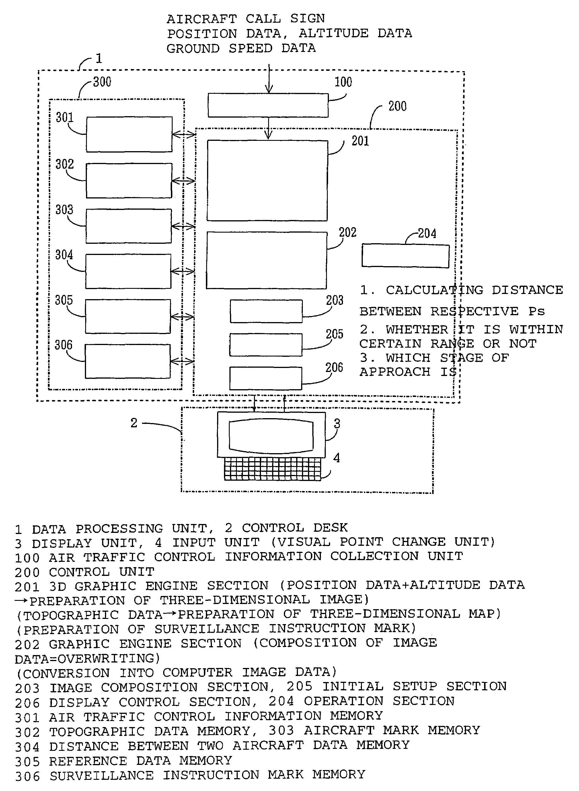
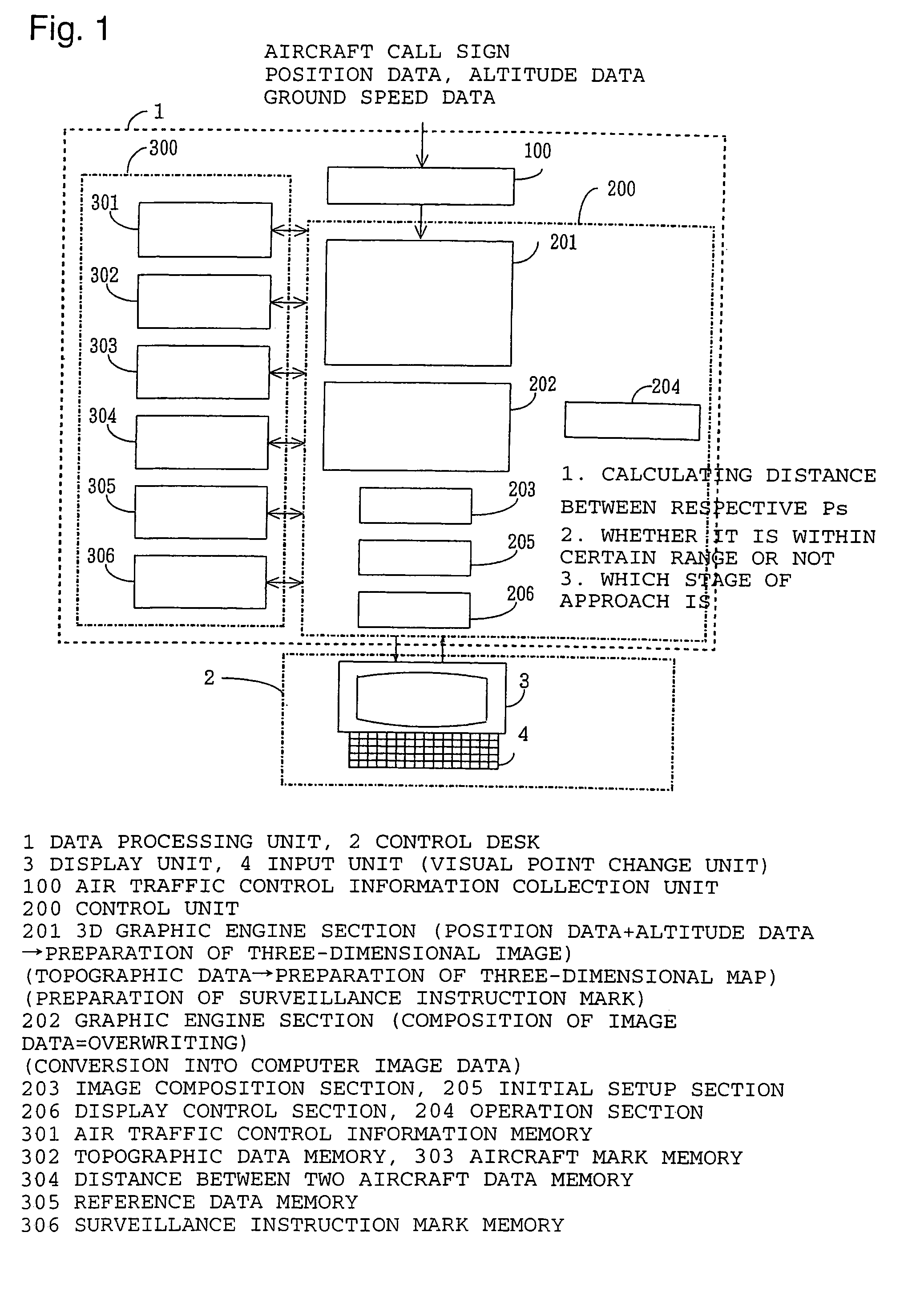
[0038]Turning now to explanation in reference to the accompanying drawings, an aircraft position display system according to the present invention generally comprises a data processing unit 1, a display unit 3 provided on a control console 2, and an input unit 4 connected to the display unit as shown in FIG. 1.

[0039]The data processing unit 1 includes an air traffic control information collection unit 100, a control unit 200 for processing collected air traffic control information for the purpose of accomplishing a desired purpose and for performing control operation, and a storage unit 300 for storing data originally prepared, data to be inputted from outside and data as a result of data processing by the control unit 200, respectively.

[0040]The air traffic control information collection unit 100 collects air traffic control information containing certain data, including the call sign (flight name), the current position, the travel direction and the ground speed of an aircraft exis...


PUM


Abstract

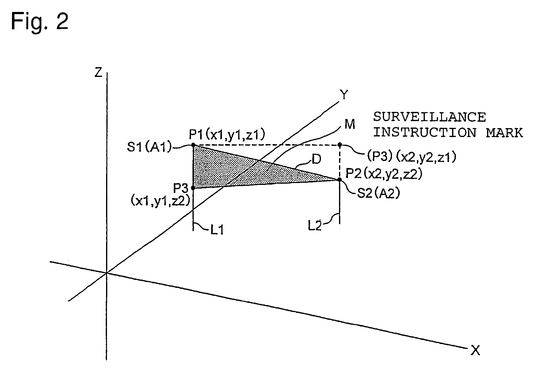
There is provided a method for displaying aircraft positions, which is capable of effectively avoiding the occurrence of near miss or collision. The method displays the terrain of an air space under air traffic control apparently in three dimensions on a display screen, displays aircraft marks at positions on the display screen so as to correspond to the three-dimensional positions of the respective aircraft, and displays a warning mark when a distance between two aircraft is shorter than a threshold value, wherein the warning mark comprises a triangle having three apexes, which comprise the aircraft marks, and a position that is apart from the aircraft mark of one of the aircraft along a vertical line extending perpendicular to the one aircraft toward a ground surface of the terrain by a distance corresponding to an altitude difference between both aircrafts on the display screen. A certain warning mark may be displayed when protective air spaces for both aircraft are predicted to conflict each other based on flight trajectories and flight conditions.

Description

[0001]This is a continuation of application Ser. No. PCT / JP02 / 11001, filed Oct. 23, 2002.TECHNICAL FIELD[0002]The present invention relates to a method for displaying aircraft positions in a display system for air traffic control, which is capable of visually grasping the flight status of aircraft under air traffic control on a display screen, and which is particularly appropriate for the surveillance and the air traffic control of the flight status of multiple aircraft that come close to each other within a safety distance.BACKGROUND ART[0003]Tragic accidents by midair collision of aircraft have frequently occurred everywhere in the world. We have often been shocked to hear that near miss has occurred, though midair collision has not occurred fortunately.[0004]In a conventional surveillance radar system, based on air traffic control information obtained from various kinds of radars, multiple range rings indicating a distance from a reference point on a runway on a ground surface, t...

Claims


Application Information

Patent Timeline
Patent Type & Authority Patents(United States)
IPC IPC(8): G08G5/04G01S7/20G01S13/91G08G5/00
CPCG08G5/0021G08G5/0078G08G5/0052G08G5/0026
Inventor SHIOMI, KAKUICHISAITO, MASANORI
Owner REALVIZ
Learn More