Eureka AIR delivers breakthrough ideas for toughest innovation challenges, trusted by R&D personnel around the world.

Modified space-filling handset antenna for radio communication

a technology of radio communication and space-filling, which is applied in the direction of loop antennas, resonant antennas, radiating element structural forms, etc., can solve the problems of too narrow bandwidth and modest efficiency

Inactive Publication Date: 2006-04-11
NOKIA CORP
View PDF4 Cites 32 Cited by
  • Summary
  • Abstract
  • Description
  • Claims
  • Application Information

AI Technical Summary

Problems solved by technology

Especially the requirement for a small size causes difficulties.
The problems of known fractal and space-filling antennas are usually related to modest efficiency and too narrow bandwidth.

Method used


Image

  • Modified space-filling handset antenna for radio communication
  • Modified space-filling handset antenna for radio communication
  • Modified space-filling handset antenna for radio communication

Examples


Embodiment Construction

[0040]The exemplary embodiments of the invention presented in this patent application are not to be interpreted to pose limitations to the applicability of the appended claims. The verb “to comprise” is used in this patent application as an open limitation that does not exclude the existence of also unrecited features. The features recited in depending claims are mutually freely combinable unless otherwise explicitly stated.

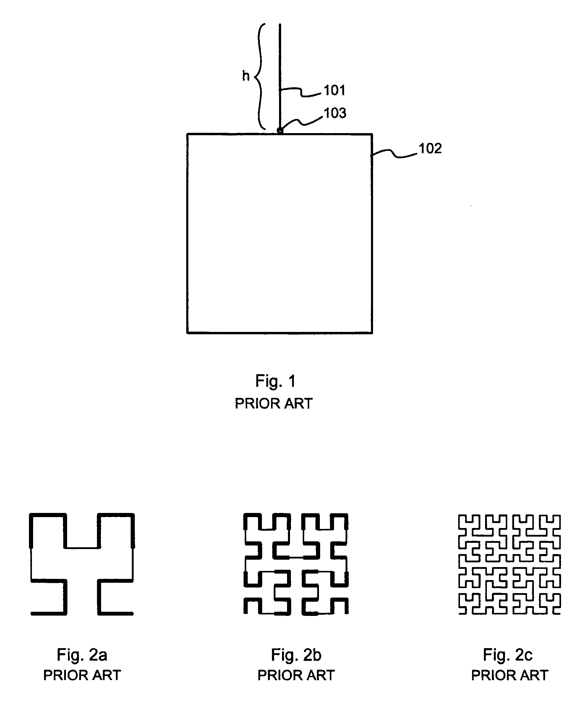
[0041]In order to enable fully understanding the invention, certain known facts of monopole antennas and space-filling curves are first discussed. FIG. 1 illustrates a very basic known monopole antenna, which comprises an essentially linear radiating antenna element 101, an associated ground plane 102 and a feed point 103. The physical end-to-end length of the radiating antenna element 101 is designated as h.

[0042]The lowest operating frequency f1 of the straight wire monopole antenna corresponds to a wavelength λ1, for which h=λ1 / 4. When an oscillating signal of...


PUM


Abstract

For manufacturing an antenna there is first defined a meandering shape. A simulated current distribution is determined for a conductive line having said meandering shape. First and second segments of said meandering shape are identified, at which said simulated current distribution exhibits first and second currents respectively, so that a vector sum of said first and second currents is essentially zero. A bend containing said first and second segments is replaced with a direct connection in said meandering shape, thus producing a pruned meandering shape. The antenna will have a radiating antenna element that has a shape equal to said pruned meandering shape.

Description

TECHNICAL FIELD[0001]The invention belongs basically to the field of small-sized radio antennas. Especially the invention is related to utilizing a space-filling curve in the design of an antenna for a portable communications device.BACKGROUND OF THE INVENTION[0002]The portable communications devices of modern telecommunications systems need antennas that should fulfil a number of requirements, some of which appear to be mutually contradictory. The antenna should be small, light and easy to manufacture in large-scale mass production at low cost. The antenna should have resonant frequencies in multiple frequency ranges, which in cellular communications systems are up to 1000 MHz apart from each other, and in FM radio reception can be as low as below 100 MHz. The input impedance of the antenna should match the impedance of an antenna port of a transceiver or receiver over a relatively wide frequency band. Losses in the antenna, caused by conduction losses in the conductive parts of th...

Claims


Application Information

Patent Timeline
Patent Type & Authority Patents(United States)
IPC IPC(8): H01Q1/38H01Q1/24H01Q5/00H01Q7/00H01Q9/16
CPCH01Q1/243H01Q9/16H01Q7/00H01Q1/38
Inventor RAHOLA, JUSSI
Owner NOKIA CORP
Why Eureka
Eureka Blog
Learn More